In this article, we will explore the PIC16F877 Watchdog TIMER (WDT) and how it can be used to improve system reliability by automatically resetting the microcontroller during faults.

Understanding Watchdog Timers (WDT) in Microcontrollers
In this project, we’re using the Watchdog Timer (WDT) with the PIC16F877A microcontroller to enhance system reliability. The WDT continuously monitors the system’s performance and resets the MCU in case of software hang-ups or failures.
What is the Watchdog Timer (WDT)?
A Watchdog Timer (WDT) ensures the microcontroller’s software runs correctly by resetting the system if it fails to respond within a set time. If the MCU doesn’t reset the WDT in time, a system reset is triggered. Most microcontrollers include internal WDTs, but external WDTs offer additional reliability, especially in mission-critical systems.

How Does a Watchdog Timer Work??
The WDT monitors the MCU’s operation by expecting periodic signals. If the MCU fails to send signals within the specified time, the WDT assumes a malfunction and triggers a system reset. The WDT operates in different modes, each offering a unique level of fault detection:
Timeout Mode: The MCU periodically resets the WDT. If it doesn’t reset within the allotted time, the WDT triggers a reset. This common mode may miss certain faults if the MCU sends signals too frequently within the timeframe.
- Window Mode: The MCU must reset the WDT within a specific time window. If the reset occurs outside this window or is missed, the
- WDT triggers a reset. This mode is ideal for applications where high fault detection accuracy is essential.
- Q&A Mode: The WDT and MCU exchange signals in a set pattern. If the WDT detects a mismatch, it triggers a reset. This mode offers the highest level of fault detection but requires synchronized communication.
Applications Requiring a Watchdog Timer
Watchdog timers are crucial in systems where failure could pose safety risks or lead to significant consequences, such as:
- Automotive Systems: Ensures vehicle safety systems operate reliably, as MCU failure could cause accidents.
- Medical Equipment: Prevents malfunctions that could endanger patient health.
Industrial Systems: Ensures continuous operation of critical processes, reducing the risk of equipment failure. - Consumer Electronics: Adds safety features in home appliances such as water heaters and stoves.
PIC16F877 Watchdog Timer (WDT)
The PIC16F877A’s WDT is an independent on-chip RC oscillator that operates continuously, even in low-power modes. It maintains system stability and fault detection by resetting the MCU if software fails to clear the timer within a set period.

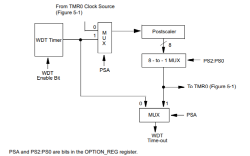
The block diagram illustrates the WDT components within the PIC16F877 microcontroller:
- WDT Timer: An on-chip RC oscillator serving as the clock source for the WDT, independent of the main system clock.
- WDT Enable Bit: A configuration bit that enables or disables WDT functionality.
- Postscaler: Divides the WDT Timer clock source to set the WDT timeout period.
- MUX: A multiplexer that selects either the WDT timeout signal or the PSA signal as the WDT timeout source.
- PSA and PS2 bits: Controls the WDT postscaler value, determining the timeout period.
PIC16F877 WDT Operation
- Normal Operation: The WDT counts down a specified period. If the MCU doesn’t “kick” or reset the WDT within this period, it triggers a device reset, allowing recovery from malfunctions and avoiding issues like infinite loops.
- Sleep Mode: In Sleep mode, the WDT remains active. When the timeout is reached, it wakes the MCU from sleep, resuming normal operation. This feature allows low-power monitoring and recovery capabilities.
PIC16F877 WDT Timeout and Configuration
The PIC16F877’s WDT has a configurable timeout period managed through the OPTION_REG register’s prescaler. Adjusting this prescaler, shared with Timer0, enables users to fine-tune the WDT countdown to meet specific timing needs. When a WDT timeout occurs, the TO bit in the STATUS register clears, allowing users to track WDT events and diagnose system issues effectively.

The WDT can be permanently disabled by clearing the WDTE bit in the OPTION_REG register, although this removes a key safety feature that supports system stability and recovery. The timeout values depend on prescaler settings, and proper configuration ensures effective fault detection and system resilience.
PIC16F877A Watchdog Timer Example with PORTB Control
This project demonstrates how to use the PIC16F877A microcontroller to control PORTB outputs while managing the watchdog timer (WDT) to prevent a reset. The program alternates PORTB output between two values and clears the WDT during a delay loop to ensure the microcontroller doesn’t reset due to the WDT overflow.
Configuration and Initialization
This section sets up the configuration bits for the PIC16F877A microcontroller. These settings include enabling the WDT, disabling the power-up timer (PWRT), and setting the oscillator to the XT configuration. It also configures the WDT prescaler for a 1:32 ratio, ensuring the WDT does not reset too frequently.
#include <xc.h>

// Configuration bits
#pragma config FOSC = XT        // Oscillator Selection bits (XT oscillator)
#pragma config WDTE = ON        // Watchdog Timer Enable bit (WDT enabled)
#pragma config PWRTE = OFF      // Power-up Timer Enable bit (PWRT disabled)
#pragma config BOREN = ON       // Brown-out Reset Enable bit (BOR enabled)
#pragma config LVP = OFF        // Low-Voltage Programming Enable bit (Low-voltage programming disabled)
#pragma config CPD = OFF        // Data EEPROM Memory Code Protection bit (Data EEPROM code protection off)
#pragma config WRT = OFF        // Flash Program Memory Write Enable bits (Write protection off)
#pragma config CP = OFF         // Flash Program Memory Code Protection bit (Code protection off)

#define _XTAL_FREQ 4000000      // Assume 4MHz crystal frequency, adjust if different
Watchdog Timer and Delay Function
This section defines a function to create a longer delay while also clearing the WDT to avoid a reset. The long_delay_with_wdt function waits for the specified time (in milliseconds) while calling CLRWDT() to reset the WDT.
// Function to create a longer delay while still clearing the watchdog timer
void long_delay_with_wdt(unsigned int delay_ms) {
    unsigned int i;
    for (i = 0; i < delay_ms; i++) {
        __delay_ms(1);          // 1 ms delay
        CLRWDT();  // Clear the watchdog timer every millisecond
    }
}
Main Function: Control PORTB and Manage WDT
In the main loop, the program configures all the PORTB pins as outputs, then alternates between two 8-bit values (0x0F and 0xF0) with a 1-second delay between changes. The delay is managed by the long_delay_with_wdt function to ensure the WDT is regularly cleared, preventing an unintended reset.
void main() {
    // Set up the watchdog timer prescaler (1:32)
    OPTION_REGbits.PSA = 0;     // Prescaler is assigned to WDT
    OPTION_REGbits.PS = 0b100;  // Prescaler ratio 1:32

    TRISB = 0;                  // All PORTB pins are configured as outputs

    while(1) {
        PORTB = 0x0F;           // Set PORTB to 0x0F (00001111 in binary)
        long_delay_with_wdt(1000);  // 1 second delay while clearing WDT

        PORTB = 0xF0;           // Set PORTB to 0xF0 (11110000 in binary)
        long_delay_with_wdt(1000);  // 1 second delay while clearing WDT
    }
}
Proteus Configuration :
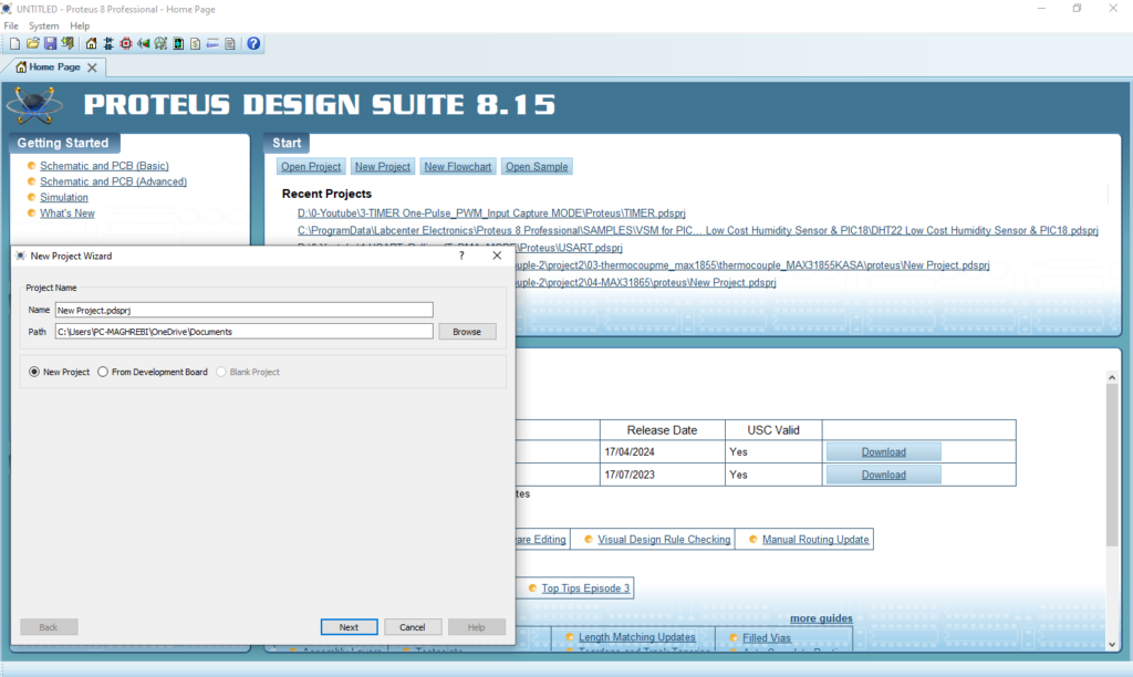
- Open Proteus & Create New Project and click next

- Click on Pick Device
- Search for PIC16F877A & LED (RED & GREEN)
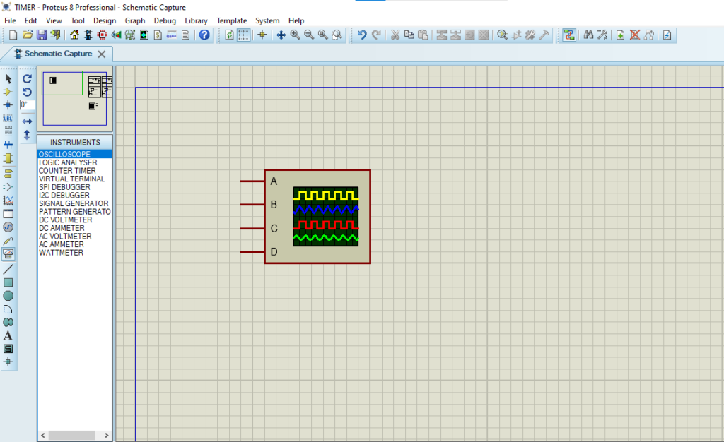
- Click on Virtual Instruments Mode then choose OSCILLOSCOPE

- Click on Terminal Mode then choose (DEFAULT & POWER &GROUND)
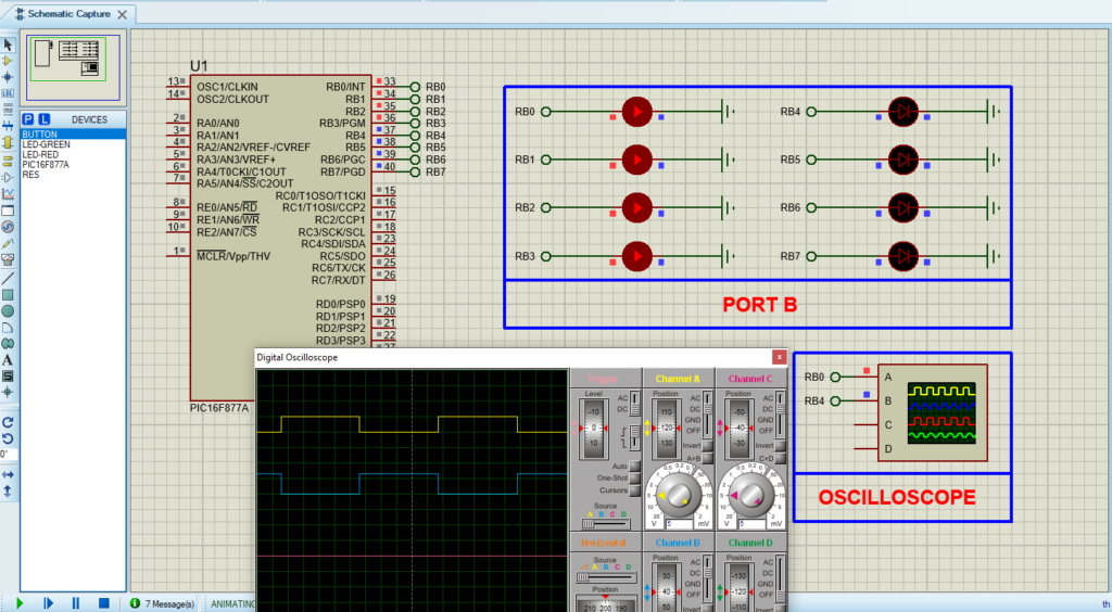
- finally make the circuit below and start the simulation

That’s all!
If you have any questions or suggestions don’t hesitate to leave a comment below
