PIC16F877 UART: A Guide to Serial Communication

by Marwen Maghrebi

This article explores the PIC16F877 UART (Universal Asynchronous Receiver-Transmitter) and its role in serial communication for embedded systems.

Features of the PIC16F877 UART project

Things used in this project

Software apps and online services:

1- MPLAB

2- Proteus 8

Introduction to Serial Communication

In embedded systems, telecommunications, and data transmission, serial communication is a process of sending data one bit at a time, sequentially, over a serial bus. This method takes one clock cycle per bit transfer. In contrast, parallel communication sends multiple bits simultaneously within a single clock cycle. Despite serial communication transmitting fewer data bits per cycle, its ability to operate at higher frequencies results in higher overall transfer rates compared to parallel communication.

Fundamental Concepts:

Various serial communication protocols exist, each with unique operational details. However, they all share a common core: shift registers. These registers are fundamental in the hardware implementation of serial communication protocols, shifting out data bit-by-bit each clock cycle.

How Shift Registers Work:

Shift registers consist of serially connected D-Flip-Flops sharing the same clock line. Data input is shifted from the input pin to the output end, transferring one bit per clock cycle. This means an 8-bit shift register takes 8 clock cycles to transfer a byte. The following animation illustrates an 8-bit shift register with serial input and output lines.

8-bit Shift Register with D-Flip-Flops

Connecting the data output of one shift register to the input of another enables serial digital data transfer between devices. The animation below demonstrates this with a pair of 4-bit shift registers, one as the transmitter and the other as the receiver, using a data and clock wire.While shift registers illustrate basic serial communication, various protocols include additional features like different data rates and error detection mechanisms. This tutorial focuses on the UART protocol, providing a solid foundation for implementing simple serial data transfers

PIC16F877 UART Serial Data Transfer with Shift Registers

Comparing Serial and Parallel Communication:

Serial communication transmits data sequentially, one bit at a time, while parallel communication sends multiple bits simultaneously over separate channels within the same clock cycle. In parallel communication, data is typically transferred over a bus consisting of multiple data lines along with synchronization signals like a clock. Unlike serial communication’s bit-by-bit transfer, parallel communication allows for the simultaneous transfer of several bits, which can speed up data transmission.

Serial Communication: Fundamentals, Protocols, and Applications:

Serial communication is fundamental in numerous applications, such as external device communication, firmware downloading, console I/O, data transmission, and debugging interfaces. Proficiency in various serial communication protocols is essential for embedded systems engineers due to their widespread use. Common protocols include USB, CAN, I2C, I2S, LIN, SPI, Ethernet, 1-Wire, and UART/USART. This tutorial focuses on UART to explain its fundamentals and mechanics, leading to data transmission between embedded MCUs.

Understanding UART: Universal Asynchronous Receiver/Transmitter:

UART, short for Universal Asynchronous Receiver/Transmitter, comprises hardware circuitry essential for serial communication, available either as standalone ICs or internal modules within microcontrollers. This communication method relies on dedicated I/O pins: RX (receiving end) and TX (transmitting end).

  • Modes of UART Communication:

    • Simplex: Allows one-way communication from transmitter to receiver.
    • Half Duplex: Involves alternating transmission and reception.
    • Full Duplex: Enables simultaneous transmission and reception.
  • UART Data Packet Structure:

    • Start Bit: Signals the beginning of a new packet.
    • Data Frame: Contains the actual data bits, typically ranging from 5 to 9 bits.
    • Parity Bit: Optional for error checking.
    • Stop Bit: Indicates the end of the data packet.
  • Baud Rate:

    • Baud rate denotes the data transfer speed in bits-per-second (bps). Common standard baud rates include 9600, 1200, 2400, 4800, 19200, 38400, 57600, and 115200 bps.

UART and USART: Understanding the Differences:

UART and USART are two essential components in serial communication, each with its own characteristics: UART: Stands for Universal Asynchronous Receiver/Transmitter. It functions as a standalone entity, suitable for low-speed applications.

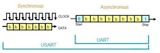
UART employs a locally generated clock, making it energy-efficient. USART: Signifies Universal Synchronous/Asynchronous Receiver/Transmitter. Unlike UART, USART supports various protocols, enabling high-speed communication. It utilizes a transmitter-generated clock but tends to consume more energy compared to UART setups.

Using UART with Microcontrollers:

The PIC16F877 UART is an essential component for serial communication, efficiently transmitting and receiving data while prioritizing the LSB (Least Significant Bit) first. This hardware-independent system ensures seamless operation by adhering to consistent data formats and baud rates. At the heart of the PIC16F877 UART functionality lies the baud rate generator, which is configurable for either x16 or x64 bit shift rates based on the BRGH bit. While hardware support for parity is absent, software implementation of the ninth data bit compensates for this limitation. Notably, asynchronous mode ceases operation during Sleep mode, ensuring energy efficiency

The UART Asynchronous module comprises vital components:

  • Baud Rate Generator
  • Sampling Circuit
  • Asynchronous Transmitter
  • Asynchronous Receiver

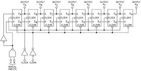
The transmitter’s core functionality revolves around the Transmit (Serial) Shift Register (TSR), which acquires data from the Read/Write Transmit Buffer (TXREG). Software intervention is necessary to load data into the TXREG register, ensuring a smooth data transmission process. Upon completion of the preceding transmission’s Stop bit, the TSR register loads the new data frame from TXREG, facilitating continuous data transfer. Notably, the TXIF flag bit signifies an interrupt condition, adjustable through the TXIE bit, while the TRMT status bit indicates TSR register emptiness, necessitating manual polling.

Transmission initiation entails setting the TXEN enable bit, coupled with data loading into the TXREG register and clock generation by the Baud Rate Generator. Flexibility exists for transmission commencement either by loading TXREG first or by simultaneous TXREG loading and TXEN enabling. Disabling TXEN mid-transmission aborts the process, resetting the transmitter and reverting the TX/RC6 pin to High-impedance state.

UART Transmitter Configuration Steps:

  1. Configure Baud Rate: Initialize the SPBRG register to achieve the desired baud rate, utilizing the BRGH bit for high-speed operation.
  2. Activate Asynchronous Serial Port: Enable the asynchronous serial port by configuring SYNC and SPEN bits.
  3. Set Pin Data Direction: Define the data direction for RX and TX pins (RC6/TX/CK and RC7/RX/DT) for UART operation.
  4. Enable UART Transmission: Activate UART transmission by setting the TXEN bit.
  5. Load Data to TXREG: Load data into the TXREG register for transmission.

Project Name: UART Communication with LED Indicators

This project showcases PIC16F877 UART communication between a microcontroller and a simulated virtual terminal using Proteus. Utilizing a PIC16F877 UART, the system establishes communication with the simulated terminal via a serial connection. Users interact with the simulated terminal, inputting messages that are transmitted to the microcontroller through UART. Visual feedback is provided by LED indicators: LED1 blinks during the wait for data transmission, and LED2 blinks upon successful message reception. Upon receiving the message, the microcontroller processes it and transmits it back to the simulated terminal for display.

Code (in C using XC8 Compiler):

Initialization

In this step, the program initializes the necessary peripherals for PIC16F877 UART communication and prepares the LEDs for visual feedback. The UART_TX_Init function configures the UART settings, including setting the baud rate for serial communication and defining the TX and RX pins. The LED_Init function configures the pins connected to the LEDs as outputs and ensures both LEDs are off at the start. This setup is crucial for establishing the microcontroller’s ability to communicate with a computer terminal and provide user feedback through the LEDs.

#include <xc.h>
#include <stdint.h>
#define _XTAL_FREQ 8000000

// Configuration bits
#pragma config FOSC = HS    // High-speed oscillator
#pragma config WDTE = OFF   // Watchdog Timer Enable (WDT disabled)
#pragma config PWRTE = OFF  // Power-up Timer Enable (PWRT disabled)
#pragma config BOREN = ON   // Brown-out Reset Enable (BOR enabled)
#pragma config LVP = OFF    // Low-Voltage (single-supply) In-Circuit Serial Programming Enable (LVP disabled)
#pragma config CPD = OFF    // Data EEPROM Memory Code Protection (Data EEPROM code protection off)
#pragma config WRT = OFF    // Flash Program Memory Write Enable (Write protection off)
#pragma config CP = OFF     // Flash Program Memory Code Protection (Code protection off)

// Define LED pins
#define LED1 RA0 // LED1 on RA0
#define LED2 RA1 // LED2 on RA1

// Function to initialize UART transmission
void UART_TX_Init(void)
{
    // Set baud rate to 9600 bps
    BRGH = 1;       // High-speed baud rate
    SPBRG = 51;     // Set SPBRG for 9600 bps with 8 MHz clock
    
    // Enable Asynchronous Serial Port
    SYNC = 0;
    SPEN = 1;
    
    // Set RX-TX Pins to be in UART mode
    TRISC6 = 0;     // TX pin (output)
    TRISC7 = 1;     // RX pin (input)
    
    // Enable UART Transmission
    TXEN = 1;
    // Enable UART Reception
    CREN = 1;
}

// Function to initialize LEDs
void LED_Init(void)
{
    TRISA0 = 0; // Set RA0 as output (LED1)
    TRISA1 = 0; // Set RA1 as output (LED2)
    LED1 = 0;   // Turn off LED1 initially
    LED2 = 0;   // Turn off LED2 initially
}

Data Transmission and Reception

This step defines functions that facilitate the transmission and reception of data over the UART interface. The UART_Write function allows for sending individual characters after confirming that the transmitter buffer is empty. The UART_Write_Text function enables the transmission of entire strings by calling UART_Write for each character. For receiving data, the UART_Read function waits for a character to arrive and reads it from the receive buffer. The UART_Read_Text function accumulates characters into a buffer until the Enter key is detected, allowing the user to input a full message. This two-way communication capability is essential for interacting with the computer terminal.

// Function to check if UART transmitter buffer is empty
uint8_t UART_TX_Empty()
{
    // Check if the output (transmitter) buffer is empty
    return TRMT;
}

// Function to transmit a single character over UART
void UART_Write(uint8_t data)
{
    // Wait until the transmitter buffer is empty
    while (!UART_TX_Empty());
    
    // Write data to the transmitter buffer
    TXREG = data;
}

// Function to transmit a string over UART
void UART_Write_Text(const char* text)
{
    while (*text != '\0') {
        UART_Write(*text++);
    }
}

// Function to receive a single character over UART
uint8_t UART_Read(void)
{
    // Wait until data is received
    while (!RCIF);
    
    // Read and return the received data
    return RCREG;
}

// Function to receive a string over UART until Enter key is pressed
void UART_Read_Text(char* buffer, uint8_t max_length)
{
    uint8_t i = 0;
    char received_char;
    
    // Receive characters until Enter key is pressed or buffer is full
    do {
        received_char = UART_Read();
        if (received_char != '\r' && received_char != '\n') {
            buffer[i++] = received_char;
        }
    } while (received_char != '\r' && received_char != '\n' && i < max_length - 1);
    
    // Null-terminate the string
    buffer[i] = '\0';
}

Main Loop Operation

In the main loop, the program continuously prompts the user to enter a message via the terminal. It first sends a prompt message while blinking LED1 to indicate that the system is ready for input. After the user enters their message, the program reads the data and blinks LED2 to signal successful receipt. The received message is then formatted and sent back to the terminal for display, surrounded by decorative lines for clarity. This ongoing loop allows for repeated interactions, enabling users to understand and engage with UART communication while providing immediate visual feedback through the LEDs. The program effectively demonstrates how microcontrollers can handle user input and respond in a straightforward manner.

// Main function
void main()
{
    // Initialize UART and LEDs
    UART_TX_Init();
    LED_Init();
    
    // Buffer to store received data
    char received_data[50];

    while (1) {
        // Transmit prompt message over UART
        UART_Write_Text("Please write your message and press enter \n");
       
        // Blink LED1 to indicate waiting for data
        LED1 = 1;
        __delay_ms(500);
        LED1 = 0;
      
        // Receive data via UART
        UART_Read_Text(received_data, sizeof(received_data));
        
        // Blink LED2 once to indicate data received
        LED2 = 1;
        __delay_ms(500);
        LED2 = 0;
        
        // Transmit received data back over UART with professional formatting
        UART_Write_Text("\r\n");
        UART_Write_Text("*********************************** \r\n");
        UART_Write_Text("Your message is: \n");
        UART_Write_Text(received_data);
        UART_Write_Text("\r\n");
        UART_Write_Text("********************************** \r\n");
    }
}

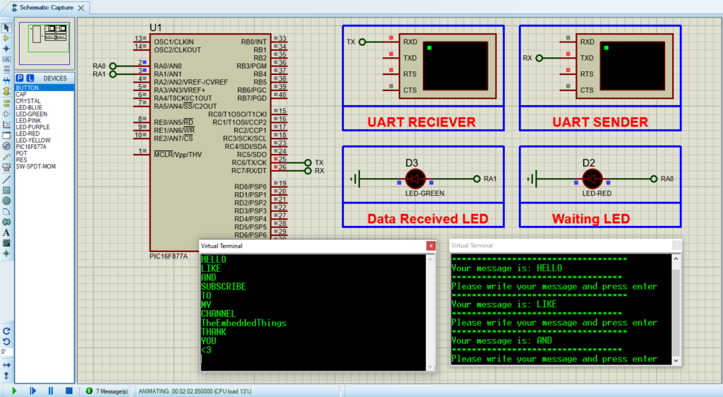
Proteus Configuration :

  • Open Proteus & Create New Project and click next

  • Click on Pick Device
  • Search for PIC16F877A & LED-RED & LED-GREEN
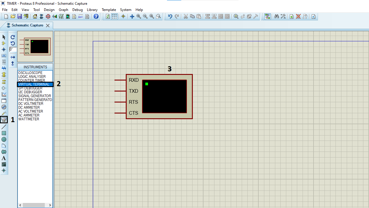
  • Click on Virtual Instruments Mode then choose  VIRTUAL TERMINAL

k on Terminal Mode then choose (DEFAULT & POWER &GROUND)

  • finally make the circuit below and start the simulation
Circuit simulation of PIC16F877 UART in Proteus.

That’s all!

If you have any questions or suggestions don’t hesitate to leave a comment below

You Might Also Like

Leave a Comment


Are you sure want to unlock this post?
Unlock left : 0
Are you sure want to cancel subscription?
-
00:00
00:00
Update Required Flash plugin
-
00:00
00:00