
In this article, we’ll explore how to configure the PIC16F877 Timer Counter Mode to achieve precise timing and counting in your microcontroller projects

Understanding Timer Counter Mode in Embedded Systems
In embedded systems, PIC16F877 timer Counter Mode plays a crucial role in facilitating precise timing and event control. This mode is one of the most versatile configurations for timers , enabling the microcontroller to count external events or pulses. Such capability proves essential in a wide range of applications, from simple user input detection to more complex data acquisition systems.
What is Counter Mode?
Counter mode is a specific timer configuration that enables a microcontroller to increment or decrement its value based on external signals. Unlike timer mode, which usually counts clock cycles, counter mode counts events triggered by external inputs. As a result, this distinction allows microcontrollers to monitor and respond to real-time occurrences more efficiently.
Key Features of Counter Mode:
- Event Detection: Counter mode detects external events, such as button presses or signal transitions. You can configure it to count rising edges, falling edges, or both, offering flexibility in how events are monitored.
- Versatile Applications: This mode is ideal for applications requiring precise event counting, including signal frequency measurement, item counting on production lines, or user interaction tracking.
- Interrupt Generation: Many microcontrollers generate interrupts based on specific counter values or events. This feature ensures the system responds immediately to important occurrences without needing to constantly check the status.
- Threshold-Based Actions: Developers can set thresholds in counter mode, which trigger actions when the counter reaches a predefined value. This is commonly used in applications like LED control, motor activation, or alarm systems.
Benefits of Using Counter Mode
- Efficiency: By offloading counting tasks to a dedicated timer, microcontrollers optimize processing resources. Meanwhile, the main application continues executing other tasks as the timer operates independently in the background.
- Precision: Counter mode provides accurate event counting, ensuring reliable performance in time-sensitive applications. This precision becomes particularly critical in systems that require synchronization with external signals.
- Reduced Latency: Thanks to interrupt capabilities, counter mode enables immediate responses to events, reducing the latency typically associated with traditional polling methods. This real-time responsiveness is crucial in fields like robotics and automation systems.
Common Applications of Counter Mode
- User Interface: Developers often use counter mode to count button presses or track rotary encoder rotations, which helps navigate menus or adjust settings in embedded devices.
- Frequency Measurement: In communication systems, counter mode is ideal for monitoring the frequency of incoming signals, ensuring precise performance.
- Production Monitoring: By using counter mode, systems can accurately track the number of items moving through a production line, which is crucial for quality control and inventory management.
- Event Logging: In safety systems, counter mode records critical events, such as how many times a safety switch has been triggered, improving response time and overall system reliability.
Event Counter with LED and Relay Control Using TMR0
This project demonstrates how to configure the Timer0 module of a PIC microcontroller in Counter Mode using the T0CKI pin. The project involves counting external pulses on RA4/T0CKI and controlling two LEDs and a relay based on the count values.
The Timer0 module is set up to operate in 8-bit Counter Mode, where it increments on every transition of an external signal applied to the T0CKI pin. The project uses thresholds to control two LEDs and a relay:
- When the count reaches the first threshold, LED1 turns on.
- At the second threshold, LED2 lights up.
- Finally, when the count exceeds the third threshold, the relay is activated.
This configuration demonstrates how Timer0 can be used as a counter to monitor external events and react accordingly by controlling output devices.
Code (in C using XC8 Compiler):
/* File: main.c
* Author: Marwen Maghrebi
*
* Description:
* This project demonstrates controlling two LEDs and a relay using the PIC16F877A microcontroller
* based on the Timer0 module. The Timer0 is configured to count external clock pulses from a button
* connected to the RA4/T0CKI pin. As the Timer0 value increments, the LEDs and relay are triggered
* at specific thresholds, providing visual feedback on the count value. The project showcases
* simple external clock counting with thresholds for controlling outputs.
*/
#include <xc.h>
#include <stdint.h>
// Configuration bits
#pragma config FOSC = HS // High Speed Crystal/Resonator
#pragma config WDTE = OFF // Watchdog Timer disabled
#pragma config PWRTE = ON // Power-up Timer enabled
#pragma config BOREN = ON // Brown-out Reset enabled
#pragma config LVP = OFF // Low Voltage Programming disabled
#pragma config CPD = OFF // Data EEPROM Memory Code Protection disabled
#pragma config WRT = OFF // Flash Program Memory Write Protection disabled
#pragma config CP = OFF // Flash Program Memory Code Protection disabled
#define _XTAL_FREQ 4000000 // 4 MHz Crystal
#define BUTTON PORTAbits.RA4 // Button connected to RA4/T0CKI
#define LED1 PORTBbits.RB0 // LED1 connected to RB0
#define LED2 PORTBbits.RB1 // LED2 connected to RB1
#define RELAY PORTBbits.RB2 // Relay connected to RB2
#define COUNT_THRESHOLD1 5 // First threshold for LED1
#define COUNT_THRESHOLD2 10 // Second threshold for LED2
#define COUNT_THRESHOLD3 15 // Third threshold for Relay
void main(void) {
// Configure ports
TRISA = 0xFF; // Set all PORTA pins as inputs
TRISB = 0; // Set all PORTB pins as outputs
// Initialize PORTB
PORTB = 0;
// Configure TMR0
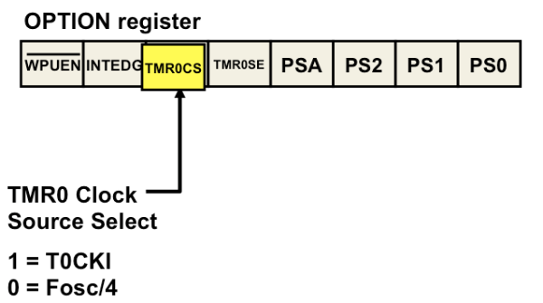
OPTION_REGbits.T0CS = 1; // TMR0 Clock Source is from T0CKI pin (RA4)
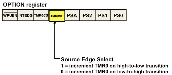
OPTION_REGbits.T0SE = 0; // Increment on low-to-high transition on RA4/T0CKI pin
OPTION_REGbits.PSA = 1; // Prescaler is not assigned to the Timer0 module
TMR0 = 0; // Clear TMR0
uint8_t prevTMR0 = 0; // To detect TMR0 changes
while(1) {
// Check if TMR0 has changed
if (TMR0 != prevTMR0) {
prevTMR0 = TMR0; // Update prevTMR0
// Check thresholds and update outputs
if (TMR0 >= COUNT_THRESHOLD1) {
LED1 = 1; // Turn on LED1
} else {
LED1 = 0; // Turn off LED1
}
if (TMR0 >= COUNT_THRESHOLD2) {
LED2 = 1; // Turn on LED2
} else {
LED2 = 0; // Turn off LED2
}
if (TMR0 >= COUNT_THRESHOLD3) {
RELAY = 1; // Activate relay
} else {
RELAY = 0; // Deactivate relay
}
}
// Optional: Add a small delay to debounce the button
__delay_ms(10);
}
}
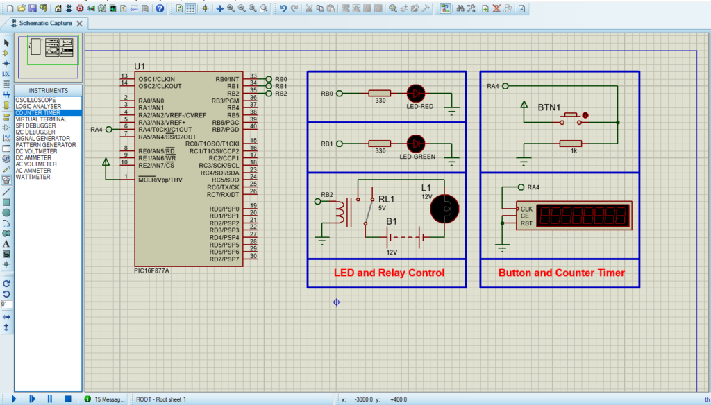
Proteus Configuration :
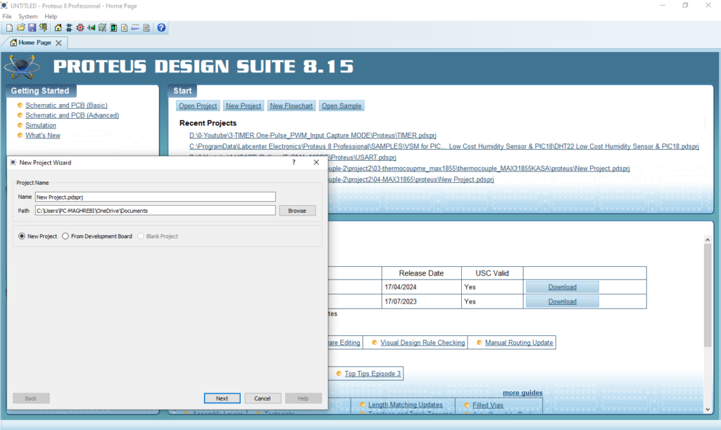
- Open Proteus & Create New Project and click next
- Click on Pick Device
- Search for PIC16F877A & RES & LED-RED & LED-GREEN & BUTTON & RELAY & LAMP
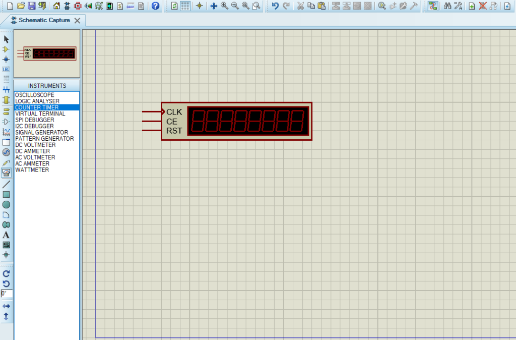
- Click on Virtual Instruments Mode then choose COUNTER TIME
- Click on Terminal Mode then choose (DEFAULT & POWER &GROUND)
- finally make the circuit below and start the simulation
That’s all!
If you have any questions or suggestions don’t hesitate to leave a comment below