
The PIC16F877 Timer is a vital component for achieving precise timing and event control in microcontroller projects.

Enhancing Embedded Systems with Timer-Based LED Control
In embedded systems, using the PIC16F877 TIMER features for LED control provides a reliable method for managing visual feedback and signaling across various applications. By strategically employing the PIC16F877 TIMER, developers can establish precise timing intervals for LED blinking, enhancing both functionality and user experience.
Understanding the PIC16F877 TIMER:
The PIC16F877 TIMER is an essential component in embedded systems, designed to measure time or generate accurate delays. While microcontrollers can create delays through loops, utilizing the PIC16F877 TIMER allows the CPU to avoid repetitive tasks, enabling it to allocate more processing power to other functions.
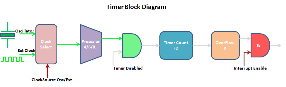
Functionality of the PIC16F877 TIMER:
A timer acts as a simple binary counter that counts clock pulses from internal or external sources. Once it reaches its maximum count, the PIC16F877 TIMER resets to zero, triggers an overflow flag, and can generate an interrupt if configured.
Overview of the PIC16F877 Timer Module:
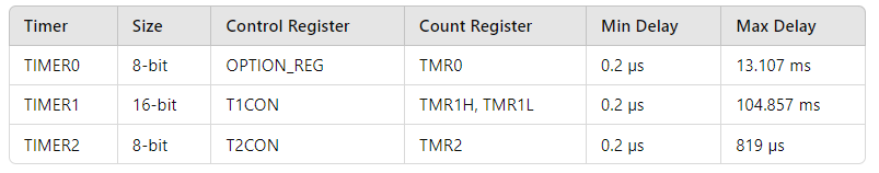
The PIC16F877A microcontroller is equipped with three independent timers, each capable of functioning as a timer, counter, or for PWM (Pulse Width Modulation) generation. The following table outlines the key features of these timers:
Timer Calculation Methodology:
To implement timer-driven LED control, calculate the timer tick based on the oscillator frequency and prescaler. Then, determine the desired delay (total time the LED should remain on or off) and compute the timer count by dividing the delay by the tick. Finally, calculate the register value to set the timer, ensuring it starts from the correct value for precise LED blinking intervals.
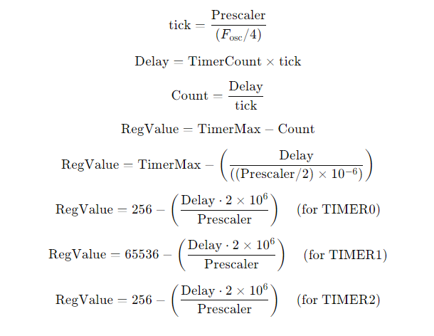
The formulas for each timer are outlined below:

Timer-Driven LED Control:
Implementing timers for LED control provides several notable advantages:
- Accurate Timing
Timers deliver high precision for generating time intervals, ensuring that LED blinking patterns are consistent and reliable. - Efficient Resource Usage
By assigning timing control to dedicated timer modules, developers can optimize resource utilization within the microcontroller, allowing the main program to perform critical tasks without the overhead of timing management. - Customization
Timer-driven control offers developers the flexibility to define specific blinking frequencies and patterns, allowing applications to meet unique requirements.
Key Implementation Considerations:
To successfully implement timer-driven LED control, developers should consider several factors:
- Timer Configuration: Properly configuring timer modules with the appropriate prescaler values and period registers is crucial for achieving the desired blinking frequency.
- Interrupt Management: Efficient handling of timer interrupts is vital for ensuring the timely execution of LED control routines while maintaining the overall operation of the microcontroller.
- Power Efficiency: In battery-powered applications, optimizing the blinking frequency and duty cycle of LEDs is essential to minimize energy consumption.
Practical Applications:
- Signaling and Indication: Timer-controlled LEDs are prevalent in various embedded systems for signaling and indication, such as alarm systems, status indicators, and user interfaces.
- Communication: Blinking LEDs serve as visual communication tools, relaying information or feedback to users. Different blinking patterns can represent various system states or error conditions.
- Visual Appeal: In applications where aesthetics are essential, such as consumer electronics and automotive displays, timer-driven LED control allows for the creation of visually captivating lighting effects and animations.
Project Name: Timer-Based LED Toggler with UART Monitoring
This code initializes multiple interrupt counters and toggles LEDs connected to different pins of the PIC16F877A microcontroller based on specific time intervals. Additionally, it implements UART communication to send a message periodically via serial transmission. Below is the breakdown of the code:
Code (in C using XC8 Compiler):
Configuration and Initialization
This section includes the necessary configuration settings, global variables, and the initialization of the UART module. It sets up the microcontroller’s configuration bits, defines the system clock frequency, and prepares the UART communication for serial data transmission.
/*
 * File: main.c
 * Author: Marwen Maghrebi
 * Description:
 * Timer-based LED toggling with UART monitoring.
 * This code initializes multiple interrupt counters and toggles LEDs connected to different pins of
 * the PIC16F877A microcontroller based on specific time intervals. Additionally, it implements UART
 * communication to send a message periodically via serial transmission.
 */

#include <xc.h>
#include <stdint.h>
#include <stdio.h>

// Configuration bits (assuming a PIC16F877A microcontroller)
#pragma config FOSC = HS
#pragma config WDTE = OFF
#pragma config PWRTE = ON
#pragma config BOREN = ON
#pragma config LVP = OFF
#pragma config CPD = OFF
#pragma config WRT = OFF
#pragma config DEBUG = OFF

// Define the system clock frequency
#define _XTAL_FREQ 8000000 // 8 MHz

// Global variables for the interrupt counts
volatile uint8_t interrupt_count1 = 0;
volatile uint16_t interrupt_count2 = 0;
volatile uint16_t interrupt_count3 = 0;
volatile uint16_t interrupt_count4 = 0;
volatile uint16_t interrupt_count5 = 0;

// UART initialization function
void UART_Init(void) {
    TRISC6 = 0; // TX pin set as output
    TRISC7 = 1; // RX pin set as input

    TXSTAbits.SYNC = 0;  // Asynchronous mode
    TXSTAbits.BRGH = 1;  // High-speed mode

    SPBRG = 51; // Baud rate 9600 for 8 MHz clock

    RCSTAbits.SPEN = 1;  // Enable serial port
    TXSTAbits.TXEN = 1;  // Enable transmission
}
UART Transmission Functions and Interrupt Service Routine (ISR)
This section contains the UART transmission functions to send data via serial communication. It also includes the ISR that handles the Timer2 overflow interrupt, toggling the LEDs based on the defined time intervals.
// UART transmit function
void UART_Transmit(char data) {
    while (!TXIF); // Wait until the transmit buffer is empty
    TXREG = data;  // Transmit the data
}

// UART send string function
void UART_SendString(const char *str) {
    while (*str) {
        UART_Transmit(*str++);
    }
}

void __interrupt() ISR() {
    if (TMR2IF) { // Check if Timer2 overflow interrupt flag is set
        TMR2IF = 0; // Clear the interrupt flag

        // Increment the interrupt counts
        interrupt_count1++;
        interrupt_count2++;
        interrupt_count3++;
        interrupt_count4++;
        interrupt_count5++;

        // Toggle LEDs based on the specified intervals
        if (interrupt_count1 >= 100) { // 10 seconds (assuming 100 ms overflow time)
            PORTBbits.RB0 ^= 1; // Toggle LED on RB0
            interrupt_count1 = 0;
        }
        if (interrupt_count2 >= 200) { // 20 seconds
            PORTBbits.RB1 ^= 1; // Toggle LED on RB1
            interrupt_count2 = 0;
        }
        if (interrupt_count3 >= 300) { // 30 seconds
            PORTBbits.RB2 ^= 1; // Toggle LED on RB2
            interrupt_count3 = 0;
        }
        if (interrupt_count4 >= 400) { // 40 seconds
            PORTBbits.RB3 ^= 1; // Toggle LED on RB3
            interrupt_count4 = 0;
        }
    }
}
Main Function and Loop
This section includes the main function where the microcontroller is configured. It initializes the Timer2 and enters the infinite loop that periodically sends messages via UART, allowing monitoring of the loop execution.
void main(void) {
    // Configure RB0, RB1, RB2, and RB3 as output
    TRISBbits.TRISB0 = 0;
    TRISBbits.TRISB1 = 0;
    TRISBbits.TRISB2 = 0;
    TRISBbits.TRISB3 = 0;

    // Turn off LEDs initially
    PORTBbits.RB0 = 0;
    PORTBbits.RB1 = 0;
    PORTBbits.RB2 = 0;
    PORTBbits.RB3 = 0;

    // Configure Timer2
    T2CONbits.T2CKPS = 0b11; // Prescaler 1:16
    PR2 = 124; // Load Period Register (PR2)
    TMR2 = 0; // Clear Timer2 register
    T2CONbits.TMR2ON = 1; // Turn on Timer2

    // Enable Timer2 interrupt
    PIE1bits.TMR2IE = 1; // Enable Timer2 interrupt
    INTCONbits.PEIE = 1; // Enable peripheral interrupts
    INTCONbits.GIE = 1; // Enable global interrupts

    // Initialize UART
    UART_Init();

    uint32_t loop_counter = 0;
    char buffer[32];

    while (1) {
        // Increment loop counter
        loop_counter++;

        // Create the message string
        sprintf(buffer, "LOOP EXECUTE %lu\r\n", loop_counter);

        // Send the message via UART
        UART_SendString(buffer);

        // Delay to prevent flooding the UART
        __delay_ms(1000);
    }
}
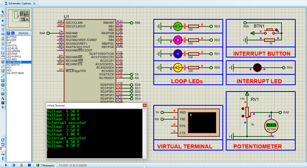
Proteus Configuration :
- Open Proteus & Create New Project and click next

- Click on Pick Device
- Search for PIC16F877A & LEDs
- Click on Virtual Instruments Mode then choose VIRTUAL TERMINAL & OSCILLOSCOPE
- Click on Terminal Mode then choose (DEFAULT & POWER &GROUND)
- finally make the circuit below and start the simulation
That’s all!
If you have any questions or suggestions don’t hesitate to leave a comment below
1 comment
[…] embedded systems, PIC16F877 timer Counter Mode plays a crucial role in facilitating precise timing and event control. This mode is […]