In this article, we will explore how to interface the PIC16F877 microcontroller with the TCN75A I2C Temperature Sensor for precise temperature monitoring.
Interfacing the TCN75A I2C Temperature Sensor with the PIC16F877 Microcontroller for Precise Thermal Monitoring in Embedded Systems
In this project, we will explore how to interface the TCN75A I2C temperature sensor with the PIC16F877 microcontroller for accurate temperature monitoring, ideal for embedded systems requiring precise thermal measurements.
Overview of the TCN75A I2C Temperature Sensor
The TCN75A from Microchip Technology Inc. is a highly accurate digital temperature sensor that measures temperatures from –40°C to +125°C with a typical accuracy of ±1°C. It offers flexible, user-configurable features, including adjustable temperature resolution, power-saving modes, and programmable temperature alert thresholds. The sensor supports I2C communication, allowing multiple devices to be connected to a single bus. This makes the TCN75A perfect for cost-effective, multi-zone temperature monitoring in embedded systems.
Features and Applications of the TCN75A I2C Temperature Sensor
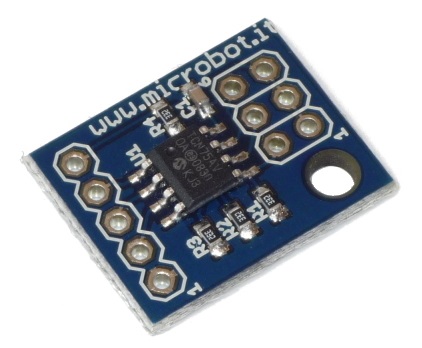
The TCN75A I2C temperature sensor offers a precise temperature-to-digital conversion with a typical accuracy of ±1°C, spanning temperatures from -40°C to +125°C. It features user-selectable resolution, ranging from 0.5°C to 0.0625°C, and operates within a voltage range of 2.7V to 5.5V. This sensor supports a low-power I2C interface, consuming just 200 µA during operation and 2 µA in shutdown mode. Ideal for various applications, the TCN75A is widely used in personal computers, office equipment, entertainment systems, and general-purpose temperature monitoring.
Block Diagram Illustrating the TCN75A I2C Temperature Sensor
The block diagram of the TCN75A provides a detailed representation of its internal components and functionality. This digital temperature sensor communicates using the I²C interface, making it easy to integrate with various systems.
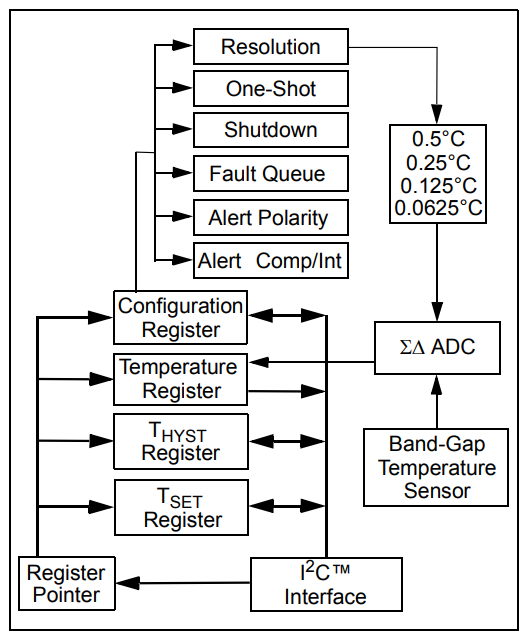
Here’s a breakdown of its functional blocks:
- The band-gap temperature sensor serves as the core, converting thermal changes into an electrical signal.
- A Sigma-Delta (ΣΔ) ADC processes this signal into a precise digital temperature reading.
- The configuration register allows customization of settings, such as resolution (from 0.5°C to 0.0625°C), operational modes (shutdown or one-shot), and alert features.
- Temperature data is stored in the temperature register, while thresholds for alerts are defined in the TSET and THYST registers.
- The alert system can function in comparator or interrupt modes, with programmable hysteresis and polarity settings.
- The I²C interface ensures seamless communication between the sensor and external microcontrollers or processors.
Temperature Measurement Capabilities of the TCN75A I2C Temperature Sensor
The TCN75A temperature sensor utilizes an integrated band-gap sensor and Sigma-Delta (ΣΔ) ADC for temperature measurement. It offers selectable resolutions from 9-bit (0.5°C) to 12-bit (0.0625°C), storing temperature data as a 2’s complement value in the Temperature Register (TA). The sensor is accessible via an I²C interface without interrupting ongoing conversions.
ADC Resolution
The TCN75A allows configurable resolutions between 9-bit and 12-bit, with higher resolutions offering improved precision and reduced quantization error. Resolution is adjustable via the CONFIG register.
Operational Modes
- Shutdown Mode
- Minimizes power consumption to 2 µA (max) by halting operations, including sampling.
- The I²C interface remains active for register access.
- The device stays in this mode until continuous conversion is re-enabled via the Configuration Register.
- One-Shot Mode
- Ideal for low-power applications.
- Performs a single conversion, updates the TA Register, and returns to shutdown mode.
- Example: A 9-bit conversion draws 200 µA for 30 ms.
ALERT Pin Functionality and Fault Handling
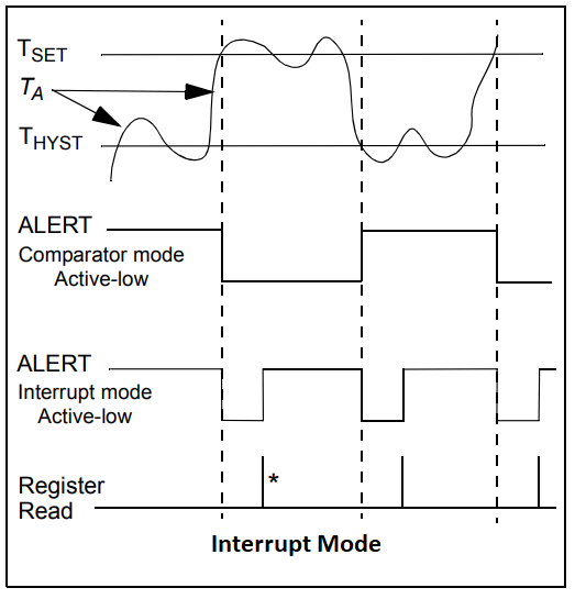
The ALERT pin supports two thermal monitoring modes:
- Comparator Mode
- Asserts ALERT when temperature exceeds the TSET threshold, deasserting after falling below THYST.
- Suitable for thermostat applications like cooling fan control.
- Interrupt Mode
- ALERT triggers upon exceeding TSET and clears on reading any register.
- Requires another read to clear when temperature falls below THYST.
- Designed for microcontroller-based interrupt systems.
- Fault Queue
Prevents false ALERT triggers by requiring multiple consecutive over-threshold conditions (up to six, configurable via the CONFIG register) before asserting ALERT.
Ensures stable clearing or re-triggering of ALERT in both Comparator and Interrupt modes, avoiding transient fluctuations.
Interfacing TCN75A Temperature Sensor with UART on PIC
This project interfaces the TCN75A temperature sensor with a PIC microcontroller via I²C communication. It continuously monitors temperature and transmits data through UART. The system operates in Default, Normal, and Safety modes, with customizable thresholds and alerts. It includes fault queue settings and hysteresis management for reliable responses. Ideal for precise temperature monitoring and timely alerts in critical applications.
I2C Driver Header File (i2c.h)
This header defines the I2C driver functions for initializing and handling I2C communication between the microcontroller and LM75 sensor.
// I2C.h
#ifndef I2C_H
#define I2C_H

#include <xc.h>
// Define constants

#define _XTAL_FREQ             16000000
#define I2C_BaudRate           100000
#define SCL_D                  TRISC3
#define SDA_D                  TRISC4

// Function prototypes
void I2C_Master_Init(void);
void I2C_Master_Wait(void);
void I2C_Master_Start(void);
void I2C_Master_RepeatedStart(void);
void I2C_Master_Stop(void);
void I2C_ACK(void);
void I2C_NACK(void);
unsigned char I2C_Master_Write(unsigned char data);
unsigned char I2C_Read_Byte(void);

#endif
UART Driver Header File (uart.h)
Defines functions to initialize UART, send and receive data, and handle text-based communication with the UART module.
//uart.h
#ifndef UART_H
#define UART_H
#include "i2c.h"
#include <xc.h>
#include <stdint.h>

void UART_TX_Init(void);
uint8_t UART_TX_Empty(void);
void UART_Write(uint8_t data);
void UART_Write_Text(const char* text);
uint8_t UART_Read(void);
void UART_Read_Text(char* buffer, uint8_t max_length);

#endif // UART_H
LM75 Sensor Driver Header File (TCN75A.h)
Provides functions to configure and operate the TCN75A sensor, including reading temperature, setting modes, and configuring thresholds.
#ifndef TCN75A_H
#define TCN75A_H

#include <xc.h>
#include "i2c.h"

// TCN75A Register Addresses
#define TCN75A_TEMP_REG      0x00
#define TCN75A_CONFIG_REG    0x01
#define TCN75A_THYST_REG     0x02
#define TCN75A_TLIMIT_REG    0x03

// Configuration Options
#define ONESHOT              0x05
#define ADC_RESO             0x04
#define F_QUEUE              0x03
#define ALERT_POL            0x02
#define COMP_INT             0x01
#define SHUTDOWN             0x00

#define COMP_MODE            0
#define INT_MODE             1

// Function Prototypes
void TCN75A_Init(uint8_t adr);
float TCN75A_ReadTemperature();
void TCN75A_SetHystTemp(float val);
void TCN75A_SetLimitTemp(float val);
void TCN75A_SetRangeTemp(float val_down, float val_up);
float TCN75A_GetLimitTemp();
float TCN75A_GetHystTemp();
void TCN75A_SetOneShot(uint8_t sw);
void TCN75A_SetResolution(uint8_t val);
void TCN75A_SetFaultQueue(uint8_t val);
void TCN75A_SetAlertPolarity(uint8_t sw);
void TCN75A_SetAlertMode(uint8_t sw);
void TCN75A_SetShutdown(uint8_t sw);
int8_t TCN75A_CheckConfig(uint8_t op);
void TCN75A_SetTemp(uint8_t reg, float value);
float TCN75A_GetTemp(uint8_t reg);
uint8_t TCN75A_CheckAlert(void);

#endif
Main Application File (main.c)
The main application file for the TCN75A sensor initializes the sensor and peripherals, reads temperature data, and handles different operational modes, as described below:
- Default Mode: Displays default temperature thresholds and checks if the current temperature exceeds the set limit.
- Normal Mode: Configures and displays temperature thresholds for normal operation (55°C – 60°C), checking if the temperature exceeds the limit.
- Safety Mode: Configures stricter thresholds for safety (65°C – 70°C), checking if the temperature exceeds the limit.
#include "TCN75A.h"
#include "i2c.h"
#include "uart.h"
#include <stdio.h>

#define SENSOR_ADDRESS 0x48 // Example I2C address of TCN75A

// Function prototypes
void setupSensorForNormalMode(void);
void setupSensorForSafetyMode(void);
void restartSensor(void);

// Global variables
float actualTemp;
float LimitTemp;
float HystTemp;
char displayText[64];

void setupSensorForNormalMode(void) {
    TCN75A_SetAlertMode(COMP_MODE);
    TCN75A_SetAlertPolarity(0);
    TCN75A_SetRangeTemp(55.0, 60);
    TCN75A_SetFaultQueue(1);
}

void setupSensorForSafetyMode(void) {
    TCN75A_SetAlertMode(INT_MODE);
    TCN75A_SetAlertPolarity(1);
    TCN75A_SetRangeTemp(65.0, 70);
    TCN75A_SetFaultQueue(2);
}

void restartSensor(void) {
    TCN75A_SetShutdown(1);
    __delay_ms(500);
    TCN75A_SetShutdown(0);
}

int main(void) {
    // Initialize I2C, UART, and TCN75A
    I2C_Master_Init();
    UART_TX_Init();
    TCN75A_Init(SENSOR_ADDRESS);
    UART_Write_Text("TCN75A initialized");

    // Main loop
    while (1) {
        // Read the current temperature
        actualTemp = TCN75A_ReadTemperature();
        sprintf(displayText, "Temp: %.1f C\n\r", actualTemp);
        UART_Write_Text(displayText);

        // Switch based on button states
        if (RB0 == 1) { // Default Mode
            UART_Write_Text("Default Mode\n\r");
            // Get default temperature thresholds
            sprintf(displayText, "Default LimitTemp: %.1fC, Hysteresis: %.1fC\n\r", TCN75A_GetLimitTemp(), TCN75A_GetHystTemp());
            UART_Write_Text(displayText);
            if (actualTemp > TCN75A_GetLimitTemp()) {
                UART_Write_Text("You crossed the Default LimitTemp\n\r");
            }
        }
        else if (RB1 == 1) { // Normal Mode
            UART_Write_Text("Normal Mode\n\r");
            restartSensor();
            setupSensorForNormalMode();
            sprintf(displayText, "Normal mode Thresholds: LimitTemp: %.1f C, Hysteresis: %.1f C\n\r", TCN75A_GetLimitTemp(), TCN75A_GetHystTemp());
            UART_Write_Text(displayText);
            if (actualTemp > TCN75A_GetLimitTemp()) {
                UART_Write_Text("You crossed the Normal Mode LimitTemp\n\r");
            }
        }
        else if (RB2 == 1) { // Safety Mode
            UART_Write_Text("Safety Mode\n\r");
            restartSensor();
            setupSensorForSafetyMode();
            sprintf(displayText, "Safety mode Thresholds: LimitTemp: %.1f C, Hysteresis: %.1f C\n\r", TCN75A_GetLimitTemp(), TCN75A_GetHystTemp());
            UART_Write_Text(displayText);
            if (actualTemp > TCN75A_GetLimitTemp()) {
                UART_Write_Text("You crossed the Safety Mode LimitTemp\n\r");
            }
        }

        // Delay before checking again
        __delay_ms(1000);
    }

    return 0;
}
Proteus Configuration :
- Open Proteus & Create New Project and click next
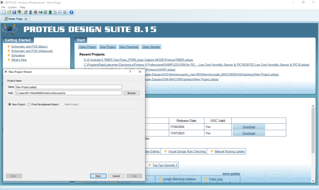
- Click on Pick Device
- Search for PIC16F877A & WITCH–3P& TCN75A
- Click on Virtual Instruments Mode then choose I2C DEBUGGER

- Click on Terminal Mode then choose (DEFAULT & POWER &GROUND)
- finally make the circuit below and start the simulation
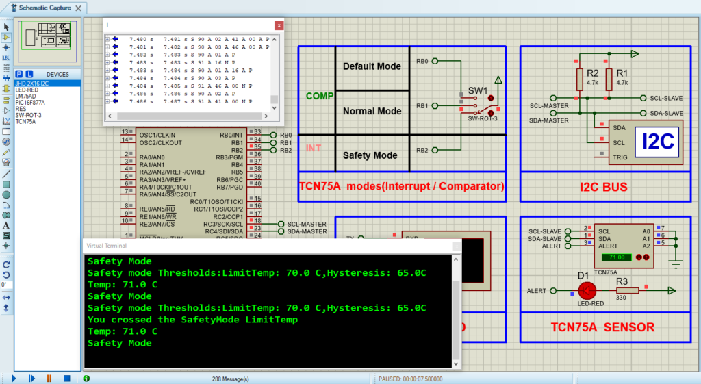
That’s all!
If you have any questions or suggestions don’t hesitate to leave a comment below
