PIC16F877 PWM: A Guide to Mastering Pulse Width Modulation

by Marwen Maghrebi

 In this article, discover how to use PIC16F877 PWM (Pulse Width Modulation) for controlling devices like motors and LEDs in your electronic projects.

Feature of the project showcasing PIC16F877 PWM

Things used in this project

Software apps and online services:

1- MPLAB

2- Proteus 8

Enhancing Embedded Systems with PWM-Based LED Control 

PIC16F877 PWM (Pulse Width Modulation) is a powerful technique for controlling LEDs and other devices in embedded systems. By varying the duty cycle of a PIC16F877 PWM signal, developers can precisely control the brightness, color, and behavior of LEDs. This technique is essential for applications requiring smooth dimming, variable brightness, or color mixing in RGB LEDs.

What is PIC16F877 PWM?

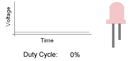
PIC16F877 PWM reduces the average power delivered by an electrical signal by chopping it into discrete parts. The two main parameters of PIC16F877 PWM are frequency and duty cycle. Frequency dictates how fast the PWM signal switches between on and off states, while the duty cycle indicates the proportion of time the signal remains on within each cycle.

How PIC16F877 PWM Works

PIC16F877 PWM operates by switching the power supply on and off at a high frequency. When the power stays on longer than it is off, the total power supplied to the device increases. This method allows for precise control over power output, making it ideal for applications such as dimming LEDs, controlling motor speeds, and generating audio signals.

Key Benefits

  • Smooth Dimming: PWM enables smooth transitions in LED brightness, avoiding the flicker that simpler on/off control methods can cause.
  • Energy Efficiency: PWM reduces power consumption by adjusting the average power delivered to the LED, making it efficient for battery-powered devices.
  • Color Control: In RGB LEDs, PWM facilitates precise control over each color channel, allowing the creation of millions of colors by varying the duty cycles of the red, green, and blue LEDs.

Applications of PWM

  • LED Dimming: Adjusting the duty cycle with PWM can control LED brightness, creating smooth dimming effects.
  • Motor Control: PWM is widely used in motor speed control, providing efficient and precise power regulation.
  • Power Regulation: PWM regulates voltage and current in power supplies, ensuring stable output for electronic devices.
  • Signal Generation: PWM can generate audio signals and other waveforms, which are useful in various communication and control systems.

PWM-Based LED Control

To utilize PWM for LED control, configure a microcontroller’s timer module to generate a PWM signal with a specific frequency and duty cycle. The duty cycle determines the proportion of time the LED is turned on within each cycle, directly influencing its brightness.

Implementation Considerations

  • Timer Configuration: Select the appropriate timer module and configure it for PWM mode. Set the desired PWM frequency and duty cycle to achieve the intended LED behavior.
  • Resolution: The resolution of the PWM signal, determined by the timer’s bit width, affects the granularity of the duty cycle adjustment. Higher resolution allows for finer control over LED brightness.
  • Frequency Selection: The PWM frequency must be high enough to avoid visible flicker in LEDs but not so high that it exceeds the microcontroller’s capabilities or affects power efficiency.

Project Name: RGB LED Control Using PWM on PIC16F877A

This project demonstrates controlling the brightness and color of an RGB LED using PWM (Pulse Width Modulation) on the PIC16F877A microcontroller. It involves setting up the microcontroller, configuring peripherals, and writing control logic for smooth color transitions.

Code (in C using XC8 Compiler):

Configuration and Initialization

The first part defines the necessary configuration bits for the PIC16F877A microcontroller, including oscillator settings and power management options. These configuration bits are crucial for setting up the microcontroller’s operation mode, ensuring it runs correctly under desired conditions. The #include statements import the required libraries, allowing access to essential functions and types. The _XTAL_FREQ macro defines the oscillator frequency to facilitate accurate delay functions later in the code.

/** 
 * File: main.c
 * Author: Marwen Maghrebi
 * Description: This project demonstrates how to control the brightness and color of an RGB LED using PWM 
 * (Pulse Width Modulation) on the PIC16F877A microcontroller. The microcontroller is set up to produce PWM signals 
 * that control the RGB LED's colors through different duty cycles, creating a smooth fading effect.
 */

// Configuration bits for PIC16F877A
#pragma config FOSC = XT        // XT Oscillator
#pragma config WDTE = OFF       // Watchdog Timer Disable
#pragma config PWRTE = OFF      // Power-up Timer Disable
#pragma config BOREN = ON       // Brown-out Reset Enable
#pragma config LVP = OFF        // Low-Voltage Programming Disable
#pragma config CPD = OFF        // Data EEPROM Code Protection Disable
#pragma config WRT = OFF        // Flash Write Protection Disable
#pragma config CP = OFF         // Flash Code Protection Disable

#include <xc.h>
#include <stdint.h>

#define _XTAL_FREQ 4000000  // Define the operating frequency of the microcontroller

Pin Definitions and PWM Initialization

This section defines the pin assignments for the RGB LED, indicating which pins on the PIC16F877A are used for each color. The PWM_Init function initializes Timer2, setting up the necessary registers for generating PWM signals. The PR2 register defines the PWM period, while the prescaler is configured to a 1:1 ratio. Finally, Timer2 is turned on, and the Capture/Compare/PWM (CCP) module is configured for PWM mode, enabling the microcontroller to generate variable duty cycle signals.

// Define pin assignments for RGB LEDs
#define REDPin   RC0  // Red LED pin
#define GREENPin RC1  // Green LED pin
#define BLUEPin  RC2  // Blue LED pin

/**
 * Initialize Timer2 for PWM
 */
void PWM_Init() {
    PR2 = 255;  // Set period register for PWM period
    T2CKPS0 = 0;  // Set prescaler to 1:1
    T2CKPS1 = 0;
    TMR2ON = 1;  // Turn on Timer2
    CCP1M3 = 1;  // Configure CCP1 module for PWM mode
    CCP1M2 = 1;
}

RGB LED Control and Main Function

This part of the code defines the RGB_LED_Control function, which sets the PWM duty cycle for each color of the RGB LED. It uses the CCPR1L and CCPR2L registers to control the red and green LEDs, respectively. Since the blue LED lacks a dedicated CCP module, additional hardware or software methods are necessary for its control.

The main function configures the LED pins as outputs and initializes the PWM settings. The main loop gradually increases the intensity of the red and green LEDs by adjusting their duty cycles from 0 to 255, resulting in a smooth transition effect. The __delay_ms(10) function creates a short delay between changes for a gradual fading effect.

/**
 * Set PWM duty cycle for each color component
 * 
 * @param red_intensity: The duty cycle for the red LED (0-255)
 * @param green_intensity: The duty cycle for the green LED (0-255)
 * @param blue_intensity: The duty cycle for the blue LED (0-255)
 */
void RGB_LED_Control(uint8_t red_intensity, uint8_t green_intensity, uint8_t blue_intensity) {
    CCPR1L = red_intensity;   // Set duty cycle for red LED using CCP1
    CCPR2L = green_intensity; // Set duty cycle for green LED using CCP2
    // Note: No CCP module available for the blue LED; additional hardware or software PWM needed.
}

/**
 * Main function
 */
void main(void) {
    // Configure RGB LED pins as output
    TRISC0 = 0; // Red LED
    TRISC1 = 0; // Green LED
    TRISC2 = 0; // Blue LED

    // Initialize PWM
    PWM_Init();

    // Main program loop
    while(1) {
        // Gradually increase the intensity of the red LED
        for (int i = 0; i <= 255; i++) {
            RGB_LED_Control(i, 0, 0);
            __delay_ms(10); // Delay for smooth transition
        }
        // Gradually increase the intensity of the green LED
        for (int i = 0; i <= 255; i++) {
            RGB_LED_Control(0, i, 0);
            __delay_ms(10); // Delay for smooth transition
        }
    }
}

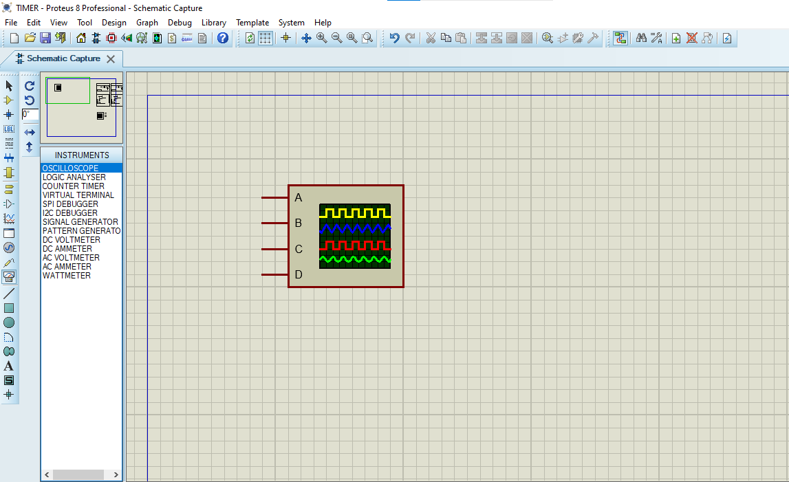
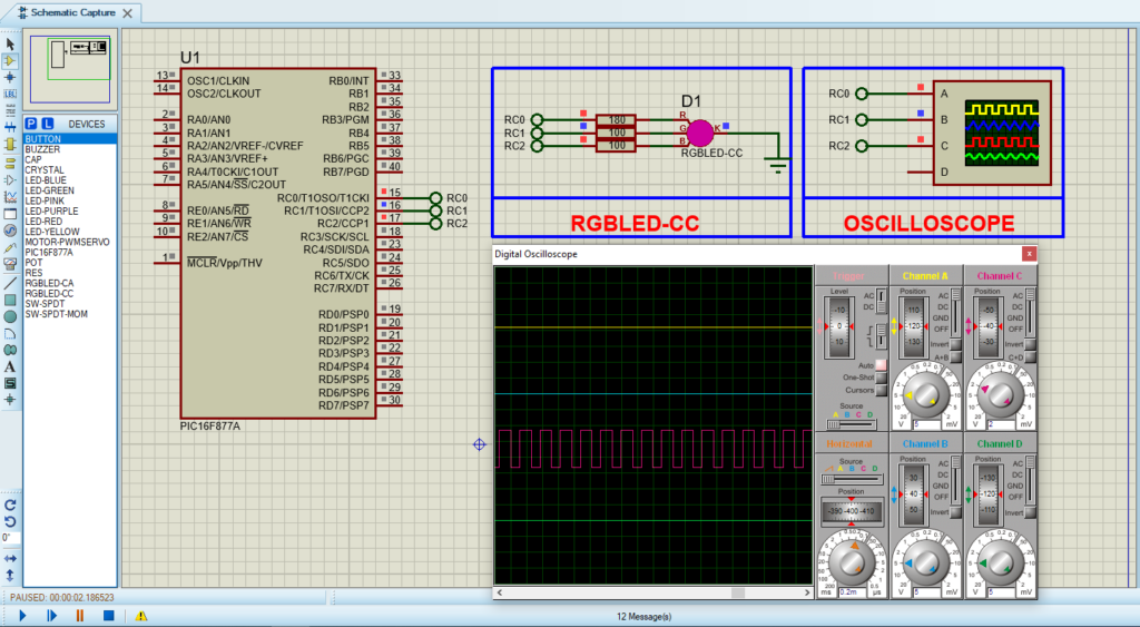
Proteus Configuration :

  • Open Proteus & Create New Project and click next

  • Click on Pick Device
  • Search for PIC16F877A & RGB
  • Click on Virtual Instruments Mode then choose  OSCILLOSCOPE

  • Click on Terminal Mode then choose (DEFAULT & POWER &GROUND)
  • finally make the circuit below and start the simulation
Circuit design for PIC16F877 PWM in Proteus simulation.

That’s all!

If you have any questions or suggestions don’t hesitate to leave a comment below

You Might Also Like

1 comment

PIC16F877 Capture and Compare Mode: A Guide to Precise Timing - The Embedded Things October 2, 2024 - 2:07 pm

[…] various modes of (CCP) Capture/Compare/PWM modules,  especially within the PIC16F877 Capture and Compare Mode, play a critical role in timing […]

Reply

Leave a Comment


Are you sure want to unlock this post?
Unlock left : 0
Are you sure want to cancel subscription?
-
00:00
00:00
Update Required Flash plugin
-
00:00
00:00