In this article, we’ll explore how to interface the PIC16F877 microcontroller with the LM75A temperature sensor and utilize its thermal watchdog feature.

Interfacing LM75A Digital Temperature Sensor with PIC16F877A: Precision Temperature Monitoring and Thermal Protection
In this project, we will explore how to interface the LM75A temperature sensor with the PIC16F877A microcontroller. The LM75A is a high-precision digital temperature sensor with a built-in thermal watchdog, ideal for temperature monitoring and protection in embedded systems.
LM75A digital temperature sensor Overview
The LM75A is a digital temperature sensor with a Sigma-delta ADC, providing precise temperature readings with a resolution of 0.125 °C. It features programmable registers for configuration, temperature limits, and hysteresis, along with an open-drain output (OS) for overtemperature alerts in comparator or interrupt mode. The device supports normal and shutdown modes, minimizing power consumption when idle. With three logic address pins, up to eight devices can share the same I2C bus. By default, it powers up in normal mode with predefined thresholds (80 °C for overtemperature and 75 °C hysteresis), making it suitable as a standalone thermostat.
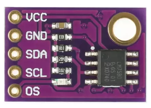
LM75A Features and Applications Summary
The LM75A is a precise, I2C-compatible temperature sensor and thermostat with enhanced resolution (0.125 °C) and wide temperature range (−55 °C to +125 °C). It operates from a 2.8 V to 5.5 V power supply, offering programmable thresholds, hysteresis, and standalone thermostat functionality. Key features include an 11-bit ADC, low power consumption (3.5 µA in shutdown mode), and robust ESD and latch-up protection. Its compact SO8 and TSSOP8 packages allow for versatile applications such as system thermal management, personal computers, industrial controllers, and electronic equipment.
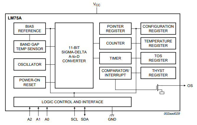
Internal Architecture of the LM75A (Block Diagrame)
The block diagram represents the internal architecture of the LM75A digital temperature sensor. Here’s a brief overview:
The main components include:
- 9-Bit Sigma-Delta ADC: Converts the temperature reading from the Silicon Bandgap Temperature Sensor into a digital value.
- 10-Bit Digital Decimation Filter: Processes the ADC output to improve noise rejection.
- Tos Set Point Register and Set Point Comparator: Allows setting a temperature threshold for generating alerts.
- Configuration Register: Stores settings for the sensor’s operation.
- Pointer Register: Manages access to the sensor’s internal registers.
- THYST Set Point Register: Stores the hysteresis temperature value for the alert threshold.
The sensor communicates with a host controller using a Two-Wire Interface (I2C-compatible) consisting of SDA and SCL lines.
Temperature Measurement and Data Storage
The LM75A measures device temperature using an on-chip bandgap sensor, achieving a resolution of 0.125°C. It performs an 11-bit analog-to-digital (A/D) conversion and stores the resulting 11-bit 2’s complement digital data in the Temp Register, which can be accessed via the I2C bus at any time. Importantly, reading the temperature data does not disrupt ongoing conversions
Operational Modes
The operational mode can be controlled by setting bit B0 in the Configuration Register. When powered on or reactivated from shutdown mode, the device automatically starts temperature conversion. The sensor supports two modes of operation:
- Normal Mode
- Temperature-to-digital conversions are executed every 100 ms.
- The Temp Register is updated after each conversion.
- Shutdown Mode
- The device becomes idle, suspending data conversion.
- The Temp Register retains the last recorded temperature data.
- The I2C interface remains active for register read/write operations.
Temperature Comparison and Output Behavior
Temperature Comparison:
The measured temperature is compared with two thresholds:
- Tos: Overtemperature Shutdown Threshold.
- Thyst: Hysteresis Threshold.
OS (Overtemperature Shutdown) Output Modes:
The OS output state changes based on the chosen Operation Mode:
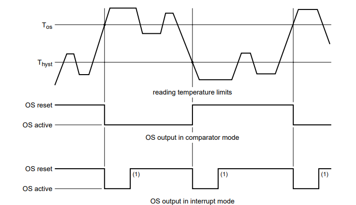
- Comparator Mode:
- Functions like a thermostat.
- Activation: When temperature > Tos.
- Reset: When temperature < Thyst.
- Suitable for applications like controlling fans or switches
- Interrupt Mode:
- Functions as a thermal interrupt.
- Activation: When temperature > Tos, and remains active until a register read occurs.
- Reset: When temperature < Thyst, reactivates on a register read.
- Fault Queue:
- OS output activates only if the fault queue condition is met.
- Fault Queue: Configurable via bits B3 and B4 in the Configuration Register.
- Defines the required number of consecutive faults for activation.
Interfacing LM75 Temperature Sensor with UART on PIC
This project demonstrates how to interface the LM75 temperature sensor with a PIC microcontroller using I2C communication. The system reads real-time temperature data, which is displayed over UART. Different modes, including Default, Normal, and Safety modes, are implemented, each with configurable thresholds for over-temperature alerts. The system monitors temperature continuously and outputs warnings if thresholds are exceeded.
Main Header File (main.h)
This header defines general constants and includes for the project. It sets the system clock frequency to 16 MHz and imports necessary standard libraries.
#ifndef MAIN_H
#define MAIN_H

#include <xc.h>
#include <stdlib.h>
#define _XTAL_FREQ 16000000

#endif
I2C Driver Header File (i2c.h)
This header defines the I2C driver functions for initializing and handling I2C communication between the microcontroller and LM75 sensor.
#ifndef I2C_H
#define I2C_H
#include "main.h"

// Function prototypes for I2C communication
void I2C_Master_Init(void);
void I2C_Master_Wait(void);
void I2C_Master_Start(void);
void I2C_Master_RepeatedStart(void);
void I2C_Master_Stop(void);
void I2C_ACK(void);
void I2C_NACK(void);
unsigned char I2C_Master_Write(unsigned char data);
unsigned char I2C_Read_Byte(void);

#endif
UART Driver Header File (uart.h)
Defines functions to initialize UART, send and receive data, and handle text-based communication with the UART module.
#ifndef UART_H
#define UART_H
#include "main.h"

// Function prototypes for UART communication
void UART_TX_Init(void);
void UART_Write(uint8_t data);
void UART_Write_Text(const char* text);
uint8_t UART_Read(void);
void UART_Read_Text(char* buffer, uint8_t max_length);

#endif
LM75 Sensor Driver Header File (LM75.h)
Provides functions to configure and operate the LM75 sensor, including reading temperature, setting modes, and configuring thresholds.
#ifndef LM75_H
#define LM75_H
#include "i2c.h"

// Function declarations for LM75 operations
void LM75_init(void);
float LM75_read(char regAddress);
void LM75_setConfig(char data);
void LM75_setShutdownMode(char enable);
void LM75_setDeviceMode(char interruptMode);
void LM75_setOSPolarity(char activeHigh);
void LM75_setFaultQueue(char faultCount);
float LM75_getHysteresisTemperature(void);
float LM75_getOSTripTemperature(void);
void LM75_setHysteresisTemperature(float temperature);
void LM75_setOSTripTemperature(float temperature);

#endif
Main Application File (main.c)
The main file initializes the LM75 sensor and peripherals, reads temperature data, and handles different operational modes:
- Default Mode: Reads factory-configured thresholds.
- Normal Mode: Configures thresholds to 60°C (OS Trip) and 55°C (Hysteresis).
- Safety Mode: Sets stricter thresholds at 70°C (OS Trip) and 65°C (Hysteresis).
#include "i2c.h"
#include "uart.h"
#include "LM75.h"
#include <stdio.h>

int main(void) {
    char buffer[64];
    // Initialize LM75 and peripherals
    LM75_init();
    UART_TX_Init();

    float currentTemp, hysteresisTemp, osTripTemp;

    UART_Write_Text("LM75 Initialized\n\r");

    while (1) {
        // Read and display current temperature
        currentTemp = LM75_read(TEMPERATURE_ADDRESS);
        sprintf(buffer, "Temp: %.1f C\n\r", currentTemp);
        UART_Write_Text(buffer);

        if (RB0 == 1) { // Default Mode
            // Read and display default thresholds
        } else if (RB1 == 1) { // Normal Mode
            // Configure and display Normal Mode thresholds
        } else if (RB2 == 1) { // Safety Mode
            // Configure and display Safety Mode thresholds
        }

        __delay_ms(1000);
    }
    return 0;
}
Proteus Configuration :
- Open Proteus & Create New Project and click next
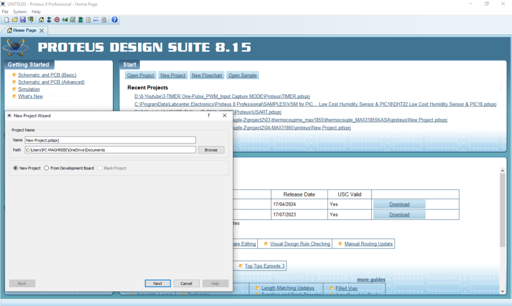
- Click on Pick Device
- Search for PIC16F877A & WITCH–3P& LM75AD
- Click on Virtual Instruments Mode then choose I2C DEBUGGER

- Click on Terminal Mode then choose (DEFAULT & POWER &GROUND)
- finally make the circuit below and start the simulation
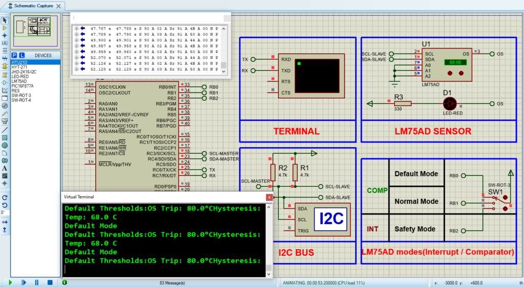
That’s all!
If you have any questions or suggestions don’t hesitate to leave a comment below
