In this article, we’ll guide you through using the PIC16F877 microcontroller with the L298 motor driver, making motor control simple and efficient.
Understanding DC Motor Control with PIC16F877A and L298 Driver
In this project, we explore how to interface the PIC16F877 microcontroller with the L298 motor driver to build a versatile and robust motor control system. This setup is especially suitable for robotics and automation applications due to its flexibility in managing both speed and direction of DC motors. Additionally, if you’re interested in advanced configurations, consider exploring related projects like STM32 L298N Motor Driver: Dual H-Bridge for DC Motors. These projects expand on the principles of PWM and H-Bridge drivers, demonstrating their effectiveness in various applications.
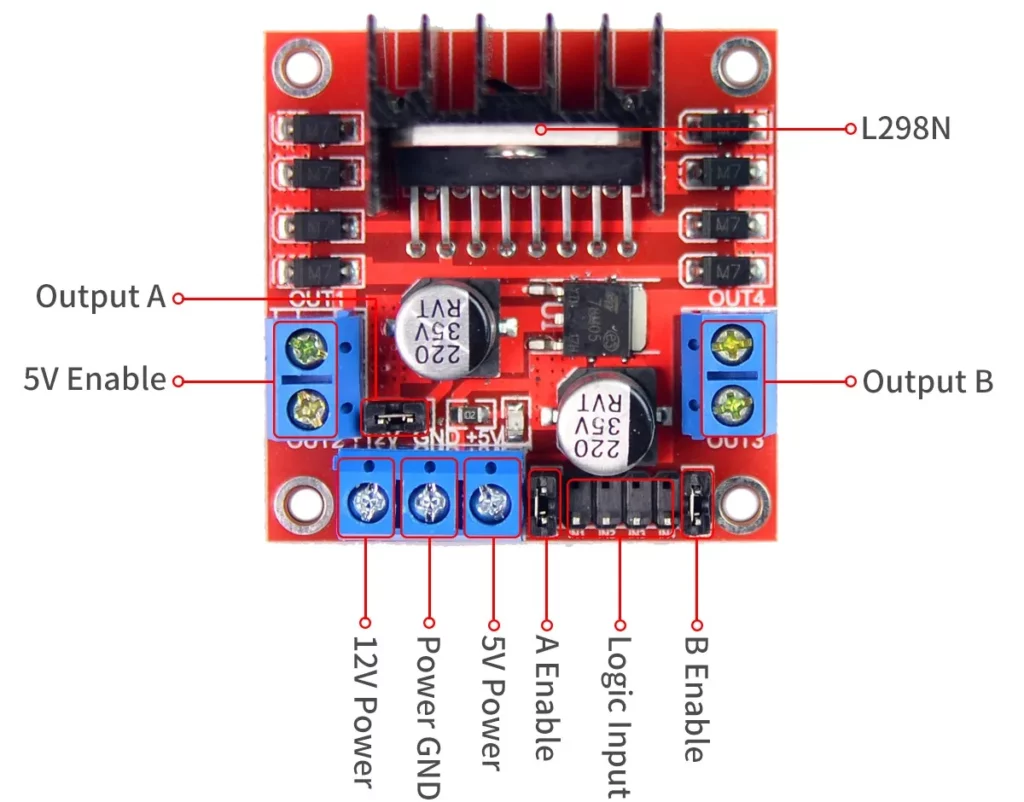
Overview of the L298 Motor Driver
The L298 motor driver is a dual H-bridge integrated circuit designed to control both DC motors and stepper motors. It offers independent control of two motors, making it possible to adjust their speed and direction. Furthermore, the L298 operates by reversing the polarity of the voltage applied to motor terminals, enabling forward and reverse rotations. With a maximum current capacity of 2A per channel and a voltage limit of 46V, this driver is a reliable choice for low-to-medium power applications.
In most cases, the L298 interfaces with microcontrollers like the PIC16F877A, which generate PWM signals to regulate speed and logical inputs to control direction. However, one must consider the design’s inherent voltage drop (up to 2V per leg), particularly when working in low-voltage environments.
L298 and DC Motor Control
When paired with DC motors, the L298 motor driver provides a simple yet effective solution for managing speed and direction. Pulse Width Modulation (PWM) adjusts the average voltage supplied to the motor, controlling its speed, while input pins determine the rotation direction. This combination makes the L298 a popular choice in applications like robotic cars, conveyor belts, and small-scale automation systems.
Nevertheless, the L298 does have some limitations, including heat generation and efficiency losses due to its voltage drop. To mitigate these issues, you can incorporate heatsinks or explore newer motor driver ICs with improved performance, especially in systems where power efficiency is critical.
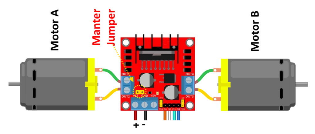
Project: Interfacing L298 Motor Driver with PIC16F877A for Dual DC Motor Control
This project demonstrates how to interface the L298 motor driver with the PIC16F877A microcontroller to control two DC motors. The setup uses Pulse Width Modulation (PWM) to adjust the speed of the motors and direction control pins for forward and backward motion. By generating PWM signals with the PIC microcontroller, the project not only showcases full control over motor operations, but also highlights its suitability for robotic and automation systems.
Configuration and Definitions
This section focuses on setting up the PIC16F877A microcontroller by configuring bits, defining pins, constants, and function prototypes to control the L298 motor driver effectively.
#include <xc.h>
#include <stdint.h>

// Configuration Bits
#pragma config FOSC = XT        // XT Oscillator
#pragma config WDTE = OFF       // Watchdog Timer Disabled
#pragma config PWRTE = OFF      // Power-up Timer Disabled
#pragma config BOREN = ON       // Brown-out Reset Enabled
#pragma config LVP = OFF        // Low-Voltage Programming Disabled
#pragma config CPD = OFF        // Data EEPROM Code Protection Disabled
#pragma config WRT = OFF        // Flash Program Write Protection Disabled
#pragma config CP = OFF         // Flash Program Code Protection Disabled

#define _XTAL_FREQ 16000000  // 16 MHz crystal frequency

// Motor Control Pins
#define ENA RC2   // PWM for Motor A
#define IN1 RD0   // Direction for Motor A
#define IN2 RD1   // Direction for Motor A
#define ENB RC1   // PWM for Motor B
#define IN3 RD2   // Direction for Motor B
#define IN4 RD3   // Direction for Motor B

// Direction Definitions
#define FORWARD 1
#define BACKWARD 2

// Function Prototypes
void setupPWM();
void setPWMDutyCycle(int speedA, int speedB);
void runMotorA(int direction, int speed);
void runMotorB(int direction, int speed);
void stopMotors();
void delay_ms(unsigned int ms);
PWM Setup and Motor Control Logic
The project utilizes Timer2 to generate PWM signals. These signals are essential for the L298 driver to control the speed of the motors. Additionally, logical functions manage motor direction, ensuring a seamless control experience.
void setupPWM() {
    T2CON = 0xFF;   // Timer2 ON, prescaler = 1:16, postscaler = 1:16
    PR2 = 255;      // Set PR2 for Timer2 maximum count
    CCP1CON = 0x0C; // Set CCP1 to PWM mode (Motor A)
    CCP2CON = 0x0C; // Set CCP2 to PWM mode (Motor B)
    CCPR1L = 0;     // Initialize PWM duty cycle for CCP1
    CCPR2L = 0;     // Initialize PWM duty cycle for CCP2
}
Motor Control Functions
The program demonstrates the ability to control the speed and direction of two DC motors. The motors operate in forward and reverse directions with programmed pauses between transitions. This showcases how to achieve precise control using the PIC16F877A microcontroller and L298 driver.
// Function to set PWM duty cycles for both motors
void setPWMDutyCycle(int speedA, int speedB) {
    CCPR1L = (unsigned char)speedA; // Set PWM duty cycle for Motor A
    CCPR2L = (unsigned char)speedB; // Set PWM duty cycle for Motor B
}

// Function to run Motor A
void runMotorA(int direction, int speed) {
    setPWMDutyCycle(speed, CCPR2L); // Update PWM for Motor A
    if (direction == FORWARD) {
        IN1 = 1; // Forward direction
        IN2 = 0;
    } else if (direction == BACKWARD) {
        IN1 = 0; // Backward direction
        IN2 = 1;
    }
}

// Function to run Motor B
void runMotorB(int direction, int speed) {
    setPWMDutyCycle(CCPR1L, speed); // Update PWM for Motor B
    if (direction == FORWARD) {
        IN3 = 1; // Forward direction
        IN4 = 0;
    } else if (direction == BACKWARD) {
        IN3 = 0; // Backward direction
        IN4 = 1;
    }
}

// Function to stop both motors
void stopMotors() {
    CCPR1L = 0; // Stop Motor A
    CCPR2L = 0; // Stop Motor B
    IN1 = 0;    // Turn off Motor A
    IN2 = 0;
    IN3 = 0;    // Turn off Motor B
    IN4 = 0;
}
Main Program Logic
This section describes the functions used to control the speed and direction of the motors, providing a seamless interface for dual motor control.
void main(void) {
    // Configure I/O Pins
    TRISC = 0x00; // PORTC as output (PWM)
    TRISD = 0x00; // PORTD as output (Direction)
    PORTC = 0x00; // Clear PORTC
    PORTD = 0x00; // Clear PORTD

    // Initialize PWM
    setupPWM();

    while (1) {
        // Run Motor A Backward and Motor B Forward at full speed
        runMotorA(BACKWARD, 255); // 100% duty cycle for Motor A
        runMotorB(FORWARD, 255); // 100% duty cycle for Motor B
        delay_ms(8000); // Run for 8 seconds

        // Stop Motors
        stopMotors();
        delay_ms(8000); // Pause for 8 seconds

        // Run Motor A Forward and Motor B Backward at full speed
        runMotorA(FORWARD, 255); // 100% duty cycle for Motor A
        runMotorB(BACKWARD, 255); // 100% duty cycle for Motor B
        delay_ms(8000); // Run for 8 seconds

        // Stop Motors
        stopMotors();
        delay_ms(8000); // Pause for 8 seconds
    }
}
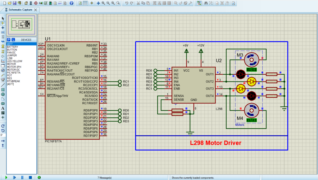
Proteus Configuration :
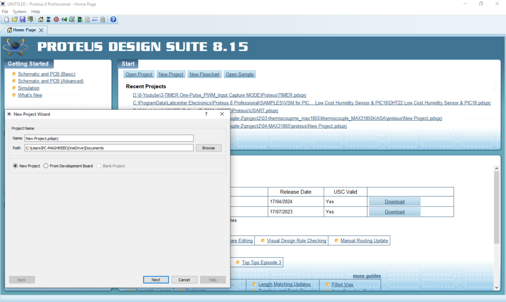
- Open Proteus & Create New Project and click next
- Click on Pick Device
- Search for PIC16F877A & L298 & DC MOTOR
- Click on Terminal Mode then choose (DEFAULT & POWER & GROUND)
- finally make the circuit below and start the simulation
That’s all!
If you have any questions or suggestions don’t hesitate to leave a comment below

1 comment
[…] In this project, we will guide you through interfacing the L9110 DC Motor Driver with the PIC16F877A microcontroller to create an efficient DC Motor Control System, perfect for robotics and automation applications. If you’re also interested in working with the L298 motor driver, don’t miss our detailed PIC16F877 L298 Motor Driver Guide […]