Table of Contents

Interrupts are fundamental to embedded systems, including the PIC16F877, providing a mechanism for the microcontroller to respond to real-time events efficiently. This article explores the concept of PIC16F877 interrupts, their importance, how they work, and their various types.
Why Use Interrupts:
Interrupts are powerful tools built into almost every microcontroller, making code easier to write and modify, especially for tasks requiring precise timing or real-time responses such as motor control or communication signals.
Embedded systems can respond to events in two primary ways: polling and interrupts.
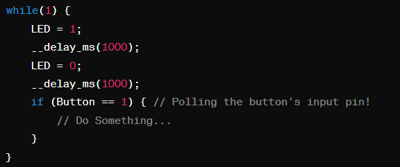
- In polling, the microcontroller continuously checks the status of an event within the main routine. For example, in a program that blinks an LED every two seconds, the microcontroller repeatedly executes code to determine if the time has elapsed to toggle the LED.
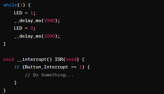
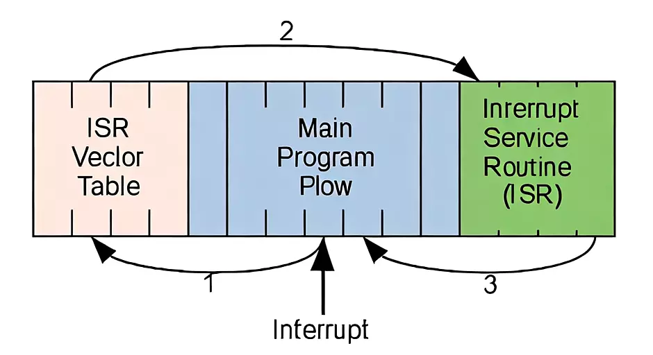
- In an interrupt-driven system, the main routine runs uninterrupted until a specific event triggers an interrupt. Upon triggering, the microcontroller pauses the main routine, executes an interrupt service routine (ISR) to handle the event, and then resumes the main routine.
Advantages of Using Interrupts:
- Efficient Code Execution: Instead of counting instructions or adding NOPs for precise timing, PIC16F877 interrupts allow for more efficient code execution. Changes in timing can be made by simply adjusting interrupt timing constants.
- Real-Time Processing: PIC16F877 interrupts ensure consistent timing, crucial for applications such as motor control or communication signals, preventing issues like jerking in motors or errors in communication routines.
- Simplified Design: Once familiar with PIC16F877 interrupts, developers often design projects around them, simplifying the overall design and speeding up development.
What is an Interrupt?:
An interrupt is an event that causes the microcontroller to pause the main code execution and execute a specific interrupt service routine (ISR). This article focuses on using an external button interrupt with the PIC16F877 to manage tasks such as toggling LEDs, sending UART messages, and utilizing ADC values.
Interrupt Service Routine (ISR):
In the realm of microcontrollers and software systems, the Interrupt Service Routine (ISR) serves a crucial role. It is referred to as a “device driver” when associated with hardware interrupts, responsible for managing interactions between the PIC16F877 microcontroller and external devices. On the other hand, in the context of software interrupts, such as exceptions, signals, or traps, the ISR is alternatively termed an “exception handler,” “signal handler,” or “trap handler.” These designations reflect the ISR’s dual function: facilitating communication between software and hardware components and managing unexpected events or conditions within the software environment.
Using Interrupt with Microcontrollers:
Types of Interrupts in Microcontrollers:
- Software Interrupts:
Programmers can intentionally trigger interrupts using specific instructions (e.g., SWI). These software-generated interrupts are useful for various debugging and control scenarios. - Hardware Interrupts:
Peripherals and modules within a microcontroller can generate interrupts to signal events like the completion of a task or an error. Hardware interrupts can be further categorized into internal and external interrupts, based on their source. - Vectored vs. Non-Vectored Interrupts:
- Vectored Interrupts: These have predefined addresses for their ISR handlers in the interrupt vector table. When an interrupt occurs, the microcontroller quickly locates and executes the appropriate ISR.
- Non-Vectored Interrupts: These use a single common interrupt vector address. The CPU saves the current execution state, jumps to this address, and executes a hard-coded ISR.
Managing Interrupts: Behind the Scenes
Within the PIC16F877A microcontroller, interrupts operate in a unique manner. Unlike vectored systems, where interrupts have specific addresses, here they share a common vector at address 0004h. To navigate this setup, a hardware-implemented program stack comes into play.
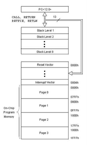
This stack operates on a Last-In-First-Out basis, holding addresses of pending instructions. When an interrupt is triggered, the CPU first stores the address of the next instruction in this stack. It then seamlessly transitions to the Interrupt Service Routine (ISR) handler code. After the ISR completes its task, the CPU effortlessly returns to the main program, utilizing the RETFIE instruction and popping the relevant address from the stack.
Understanding Interrupt Logic
The heart of interrupt functionality lies in the intricate interrupt circuitry. This digital logic circuit serves a dual purpose: configuring and managing interrupts within the microcontroller.
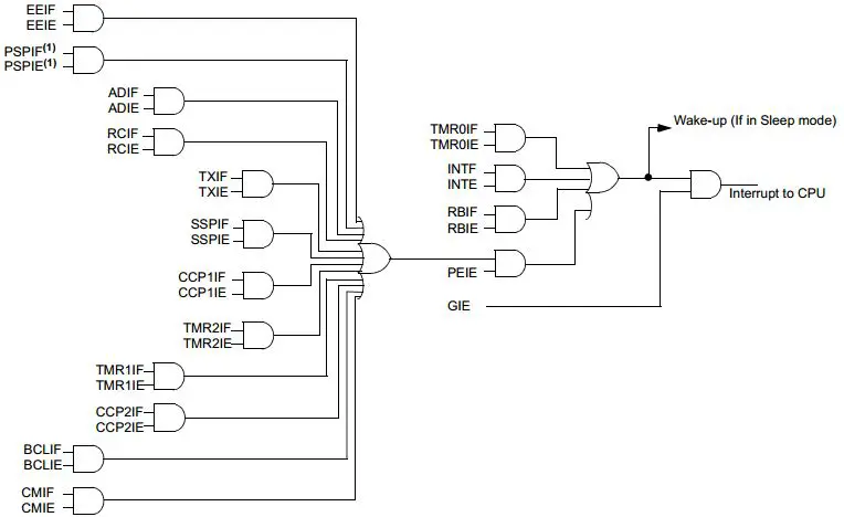
In this architecture, all interrupt sources converge onto a single interruption signal to the CPU. This unified approach simplifies the hardware but requires meticulous handling. Interrupt flag bits play a pivotal role here. They are raised when specific interrupt events occur, providing crucial cues to the CPU about the source of interruption.
Insights into Interrupt Flag Bits
Interrupt flag bits serve as silent messengers, quietly indicating when interrupt events take place. To harness their power, programmers must diligently monitor these bits. When an interrupt is flagged, it’s time to swing into action, executing the relevant ISR handler code and promptly clearing the flag bit to ready the system for subsequent interruptions.
Crafting ISR Handlers
ISR handlers are the gatekeepers of interrupt-driven operations. Nestled within specific ROM segments, these handlers are adept at deciphering interrupt sources, executing designated tasks, and tidying up afterward by clearing flag bits.
In the intricate dance of interrupts, mastery over ISR handling is paramount. It empowers developers to create responsive, efficient systems that seamlessly juggle various tasks, ensuring smooth operation even in the face of constant interruptions.
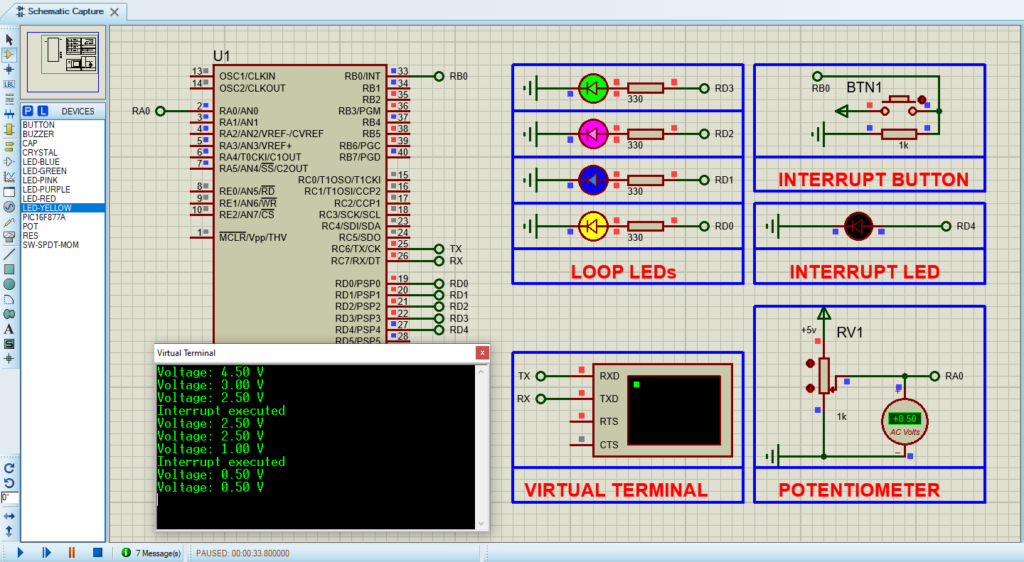
Proteus Configuration :
- Open Proteus & Create New Project and click next

- Click on Pick Device
- Search for PIC16F877A & LEDs & BUTTON