In this project, we will explore the EEPROM functionality of the PIC16F877 microcontroller. EEPROM (Electrically Erasable Programmable Read-Only Memory) serves as a type of non-volatile memory that retains data even when the microcontroller powers off. For more guidance on using an external EEPROM with the PIC16F877A, be sure to read the linked article.
Understanding EEPROM?
EEPROM retains data without power, unlike volatile memory such as RAM, which loses its contents when turned off. Furthermore, EEPROMs differ from traditional EPROMs, which require ultraviolet light for erasure; EEPROMs can be reprogrammed and erased using electrical signals. This flexibility makes EEPROM a valuable component in various electronic applications.
You can find EEPROM in two forms: external standalone IC chips or internal components integrated within microcontrollers. This tutorial focuses on using the internal EEPROM of the PIC16F877 to perform read and write operations.
Applications of EEPROM
Due to their unique features, EEPROMs find use in a wide range of applications:
- Electrical Erasability: You can erase and rewrite data without needing physical access to the chip.
- Non-volatile Storage: Data remains intact during power loss.
- User Data Retention: EEPROMs are ideal for storing configuration settings, user preferences, or other critical data that must persist across power cycles.
Common Use Cases for EEPROM
Many devices utilize EEPROMs because of their capabilities:
- Embedded Systems: They play a crucial role in devices that require memory for user-defined settings, such as passwords for secure locks.
- Data Logging: Robots or devices collecting data can leverage EEPROM to store important information that must be preserved during power loss.
- Configuration Storage: In multi-computer systems, central EEPROM can store shared data, allowing different controllers to read and update information without constant communication overhead.
Because of their broad applicability, EEPROMs are found in nearly every electronic device, either as standalone chips or integrated components within microcontrollers.
EEPROM Data Storage and LED Control with PIC Microcontroller
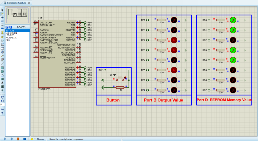
This project demonstrates how to utilize EEPROM in a PIC microcontroller for data storage. The program increments a value displayed on 8 red LEDs connected to PORTB. Additionally, it allows the user to store this value in EEPROM by pressing a button. Subsequently, the stored value can be read back and displayed on 8 green LEDs connected to PORTD.
Configuration and Main Loop
- Configuration Bits: Set various hardware options such as oscillator type and watchdog timer behavior.
- Port Configuration: Configure PORTB as output to control the 8 red LEDs and PORTD as output for the 8 green LEDs. Configure PORTA as input to read a button press.
- Main Loop: Continuously increments the value on PORTB every 100 ms. When the button on PORTA (RA2) is pressed, the program writes the value from PORTB to EEPROM and reads it back to display on PORTD.
#include <xc.h>

// Configuration bits: Adjust these according to your specific needs
#pragma config FOSC = XT        // Oscillator Selection bits (XT oscillator)
#pragma config WDTE = OFF       // Watchdog Timer Enable bit (WDT disabled)
#pragma config PWRTE = ON       // Power-up Timer Enable bit (PWRT enabled)
#pragma config BOREN = ON       // Brown-out Reset Enable bit (BOR enabled)
#pragma config LVP = OFF        // Low-Voltage Programming Enable (RB3 is digital I/O)
#pragma config CPD = OFF        // Data EEPROM Memory Code Protection (off)
#pragma config WRT = OFF        // Flash Program Memory Write Enable (off)
#pragma config CP = OFF         // Flash Program Memory Code Protection (off)

#define _XTAL_FREQ 4000000      // Assume 4MHz crystal frequency

// Function prototypes
void EEPROM_Write(unsigned char address, unsigned char data);
unsigned char EEPROM_Read(unsigned char address);

void main() {
    // Set up the ports
    ADCON1 = 0x06;  // Configure all pins as digital I/O
    TRISB = 0x00;   // Set PORTB as output (for red LEDs)
    TRISD = 0x00;   // Set PORTD as output (for green LEDs)
    TRISA = 0xFF;   // Set PORTA as input (for button)

    PORTB = 0;      // Initialize PORTB
    PORTD = 0;      // Initialize PORTD

    // Read initial value from EEPROM and display on PORTD
    PORTD = EEPROM_Read(5);  // Read from EEPROM at address 5

    while(1) {
        PORTB++;            // Increment PORTB value (light up red LEDs)
        __delay_ms(100);    // 100ms delay

        // Check if MEMO button (RA2) is pressed
        if (PORTAbits.RA2) {
            EEPROM_Write(5, PORTB);  // Write current PORTB value to EEPROM
            PORTD = EEPROM_Read(5);  // Read the value back and display on PORTD

            // Wait for button release to avoid multiple writes
            while(PORTAbits.RA2);    // Wait for button release
            __delay_ms(20);          // Simple debounce
        }
    }
}
EEPROM Functions
EEPROM_Write: This function writes a byte of data to a specified address in EEPROM. It waits for any previous write operation to complete, sets the address and data, enables write access, and executes the write operation with a specific sequence.
EEPROM_Read: This function reads a byte of data from a specified address in EEPROM. It sets the address and then triggers the read operation, returning the data stored at that address.
void EEPROM_Write(unsigned char address, unsigned char data) {
    while(EECON1bits.WR);    // Wait for write completion
    EEADR = address;         // Set address register
    EEDATA = data;           // Set data register
    EECON1bits.EEPGD = 0;    // Point to data memory
    EECON1bits.WREN = 1;     // Enable write

    INTCONbits.GIE = 0;      // Disable interrupts
    EECON2 = 0x55;           // Write 55h
    EECON2 = 0xAA;           // Write AAh
    EECON1bits.WR = 1;       // Begin write operation
    INTCONbits.GIE = 1;      // Enable interrupts

    EECON1bits.WREN = 0;     // Disable write
}

unsigned char EEPROM_Read(unsigned char address) {
    EEADR = address;         // Set address register
    EECON1bits.EEPGD = 0;    // Point to data memory
    EECON1bits.RD = 1;       // Read EEPROM
    return EEDATA;           // Return data
}
Proteus Configuration :
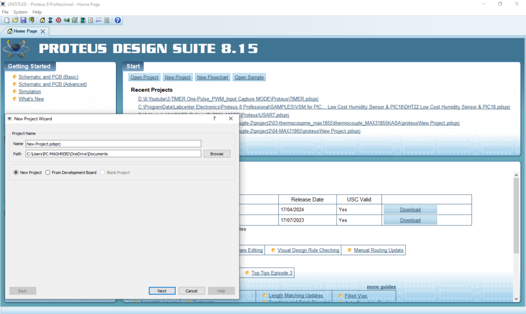
- Open Proteus & Create New Project and click next

- Click on Pick Device
- Search for PIC16F877A & LEDs (red – green) & Resistor & BUTTON
- Click on Terminal Mode then choose (DEFAULT & POWER &GROUND)
- finally make the circuit below and start the simulation

That’s all!
If you have any questions or suggestions don’t hesitate to leave a comment below


1 comment
[…] communication to reliably store and retrieve data for long-term use. For insights into using the internal EEPROM on the PIC16F877A, check out the linked […]