In this article, we will explore how to interface the PIC16F877 microcontroller with I2C external EEPROM for reliable data storage and retrieval.

In this project, we’ll connect the PIC16F877A microcontroller to the 24C64 I2C external EEPROM. This setup allows efficient communication to reliably store and retrieve data for long-term use. For insights into using the internal EEPROM on the PIC16F877A, check out the linked article.
I2C EEPROM 24C64
The 24C64 I2C external EEPROM offers 8kB of storage (65,536 bits), organized into 8192 bytes. Optimized for low power and voltage, it’s ideal for data logging and configuration storage in embedded systems. Its cascadable design allows multiple 24C64 chips to connect on a single I2C bus, managed by microcontrollers like the PIC16F877A.

Pinout and Operational Functions
- Serial Clock (SCL): This pin receives clock pulses to synchronize data transfer on the I2C bus. The positive edge of the clock signal shifts data into the EEPROM, while the negative edge shifts data out.
- Serial Data (SDA): SDA is a bidirectional data line for I2C communication. As an open-drain line, it allows multiple devices to share the same data connection.
- Device/Page Addresses (A2, A1, A0): These pins configure the device’s address on the I2C bus. With three address bits, up to eight 24C64 EEPROMs can be used on the same bus.
- Write Protect (WP): When tied to ground, WP allows normal read and write operations across the entire memory. When connected to VCC, WP locks the upper section of memory, preventing write operations.

Addressing and Configuring for I2C external EEPROM Communication
To communicate with the I2C external EEPROM, an 8-bit device address word is sent after a start condition. This address word comprises the following elements:
- A fixed binary sequence (1010) for the initial four bits, standard for I2C EEPROMs.
- Three bits (A2, A1, A0) for setting unique device addresses on the bus, matching the physical configuration of the EEPROM’s pins.
- A final bit that selects read (1) or write (0) operations.
When the PIC16F877A initiates communication with the EEPROM, it sends this device address. If there’s a match, the EEPROM acknowledges by outputting a zero on the SDA line.
Writing Data to the 24C64 EEPROM
- Single-Byte Write To write a single byte of data, follow these two steps:
- The PIC16F877A sends the device address, then specifies the memory address where the byte will be stored.
- The data byte is sent, and the EEPROM starts an internal write cycle (tWR). During this time, the EEPROM cannot respond until the write is complete.
- Page Write For writing larger amounts of data, the 24C64 allows you to write up to 32 bytes in one go. After sending the first byte, you can send up to 31 more bytes continuously without stopping. The EEPROM automatically increases the memory address for each byte until the end of the page is reached.
Important Considerations for Write Operations If you try to write more data than the page can hold, the EEPROM will overwrite the beginning of the page.
Reading Data from the 24C64 EEPROM
- Current Address Read : The 24C64 EEPROM maintains a pointer to the last accessed memory location, incrementing it after each operation. By issuing a read command, the EEPROM outputs data from the current address, making it ideal for applications that require sequential data reading.
- Random Address Read : For random access, a dummy byte write is first sent to set the desired address. Following this, a new start condition initiates a read operation, allowing the microcontroller to retrieve data from any specific address within memory.
- Sequential Read:A sequential read extends the current or random read operation by continuously outputting data while the microcontroller acknowledges each byte. When the memory address reaches its limit, it rolls over, continuing from the beginning, providing a cyclical read for large data streams.
Interfacing a 24C64 EEPROM with PIC16F877A: Write and Read Operations
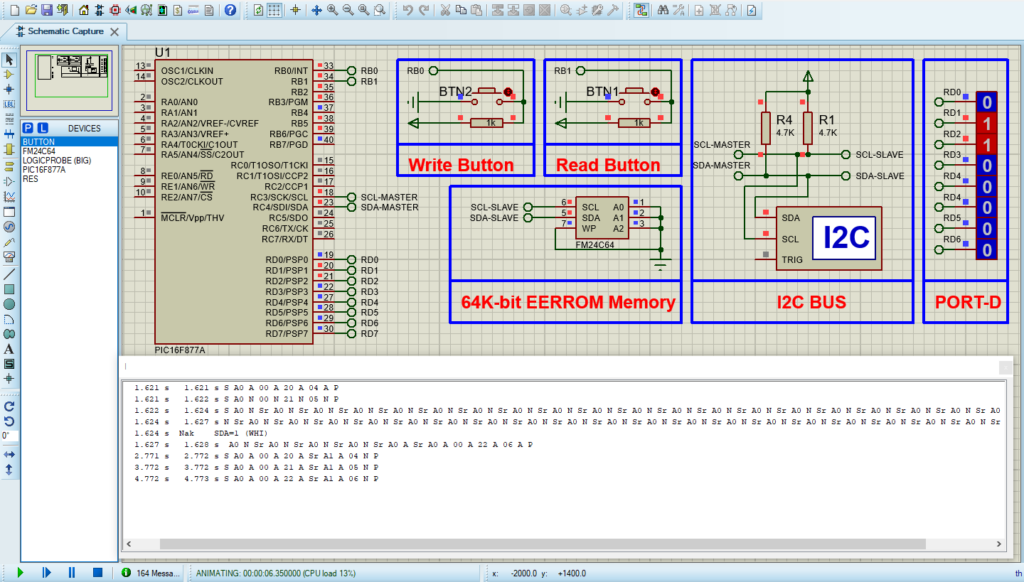
This project involves interfacing a 24C64 external EEPROM with a PIC16F877A microcontroller using I2C communication. The system features two buttons: one for writing data to the EEPROM and another for reading the data back. The results are displayed in binary format on an 8-bit output connected to PORTD.
Configuration and Initialization
This section configures the microcontroller’s ports and initializes I2C communication with the EEPROM. It also defines the button connections and sets the initial values for the EEPROM address and data.
#include <xc.h>
#include "i2c.h"
#include "eeprom.h"

#pragma config FOSC = HS        // Oscillator Selection bits (HS oscillator)
#pragma config WDTE = OFF       // Watchdog Timer Enable bit (WDT disabled)
#pragma config PWRTE = OFF      // Power-up Timer Enable bit (PWRT disabled)
#pragma config BOREN = OFF      // Brown-out Reset Enable bit (BOR disabled)
#pragma config LVP = OFF        // Low-Voltage (Single-Supply) In-Circuit Serial Programming Enable bit
#pragma config CPD = OFF        // Data EEPROM Memory Code Protection bit
#pragma config WRT = OFF        // Flash Program Memory Write Enable bits
#pragma config CP = OFF         // Flash Program Memory Code Protection bit

#define _XTAL_FREQ 16000000

#define WRITE_BUTTON RB0  // Define RB0 as the write button
#define READ_BUTTON RB1   // Define RB1 as the read button

void main(void) {
    I2C_Master_Init(100000);  // Initialize I2C Master at 100kHz

    unsigned int Address = 0x0020;  // Start address for EEPROM
    unsigned char Data = 0x04;       // Initial data to write

    TRISB = 0x03;   // Set RB0 and RB1 as inputs (buttons)
    TRISD = 0x00;   // Set PORTD as output for display
Write and Read Operations
This section handles the main logic for writing to and reading from the EEPROM. When the write button is pressed, it writes sequential data to the EEPROM. When the read button is pressed, it reads back the data and displays it on PORTD.
    while (1) {
        if (WRITE_BUTTON == 0) {  // Check if write button is pressed
            __delay_ms(20);       // Debounce delay
            if (WRITE_BUTTON == 0) {  // Confirm button press
                // Write data to EEPROM
                EEPROM_Write(Address++, Data++);  // Write first data
                EEPROM_Write(Address++, Data++);  // Write second data
                EEPROM_Write(Address, Data);        // Write last data
                __delay_ms(1000);  // Delay to prevent multiple writes
            }
        }

        if (READ_BUTTON == 0) {  // Check if read button is pressed
            __delay_ms(20);      // Debounce delay
            if (READ_BUTTON == 0) {  // Confirm button press
                Address = 0x0020;   // Reset address to start of data
                // Read data from EEPROM and display on PORTD
                PORTD = EEPROM_Read(Address++);  // Read first data
                __delay_ms(1000);
                PORTD = EEPROM_Read(Address++);  // Read second data
                __delay_ms(1000);
                PORTD = EEPROM_Read(Address);      // Read last data
            }
        }
    }
}
Proteus Configuration :
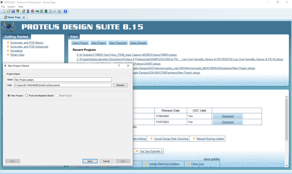
- Open Proteus & Create New Project and click next

- Click on Pick Device
- Search for PIC16F877A & FM24C64 & Resistor & BUTTON & LOGICPROB
- Click on Virtual Instruments Mode then choose I2C DEBUGGER

- Click on Terminal Mode then choose (DEFAULT & POWER &GROUND)
- finally make the circuit below and start the simulation

That’s all!
If you have any questions or suggestions don’t hesitate to leave a comment below

1 comment
[…] memory that retains data even when the microcontroller powers off. For more guidance on using an external EEPROM with the PIC16F877A, be sure to read the linked […]