PIC16F877 I2C Communication

by Marwen Maghrebi

In this article, we cover PIC16F877 I2C communication and how to easily implement it in your projects.

Featured image of the PIC16F877 I2C communication project.

Things used in this project

Software apps and online services:

1- MPLAB

2- Proteus 8

Understanding PIC16F877 I2C Communication 

Introduction to I2C Communication:

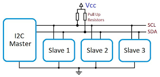
I2C (Inter-Integrated Circuit) is a widely used, multi-master, multi-slave, synchronous, bidirectional, half-duplex serial communication bus. Philips Semiconductors (now NXP) originally developed I2C in 1982. Some microcontrollers, like those from Atmel AVR, refer to it as Two-Wire Interface (TWI). This protocol operates with just two lines: the serial data line (SDA) and the serial clock line (SCL).

What is I2C?

I2C facilitates communication between multiple devices using only two lines, making data transfer and device management efficient. It uses open-drain (or open-collector) output drivers, requiring both the SDA and SCL lines to be set as inputs. Because these lines remain in high-impedance mode when not driven, I2C ensures reliable communication.

Key Features of the I2C Busl:

  • Two Bus Lines: Requires only two lines—SDA and SCL.
  • Addressable Devices: Each device connected to the bus is software-addressable by a unique address, supporting master-slave communication.
  • Multi-Master Capability: Supports multiple masters with collision detection and arbitration to prevent data corruption.
  • Data Transfer Rates:
    • Standard-mode: Up to 100 kbit/s
    • Fast-mode: Up to 400 kbit/s
    • Fast-mode Plus: Up to 1 Mbit/s
    • High-speed mode: Up to 3.4 Mbit/s
    • Ultra Fast-mode (unidirectional): Up to 5 Mbit/s
  • Spike Filtering: On-chip filtering rejects spikes on the bus data line, preserving data integrity.
  • Bus Capacitance: The number of ICs connected to the same bus is limited only by maximum bus capacitance, with higher capacitance allowed under certain conditions.

I2C Protocol Overviewl:

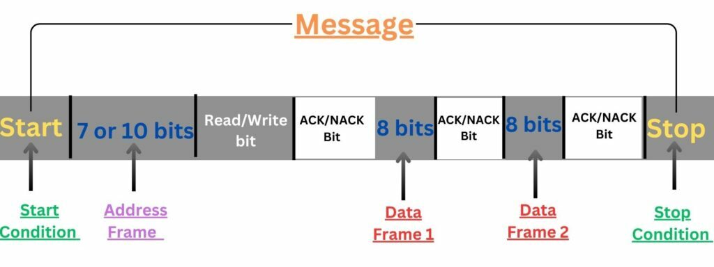
The I2C protocol operates based on several critical conditions, including start and stop conditions, address transmission, data transfer, and acknowledgment signals.

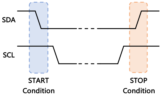
Start and Stop Conditions

  • Start Condition (S): A high-to-low transition on the SDA line while SCL is high.
  • Stop Condition (P): A low-to-high transition on the SDA line while SCL is high.
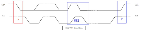
  • Repeated Start Condition (Sr): Used to maintain control of the bus without releasing it.

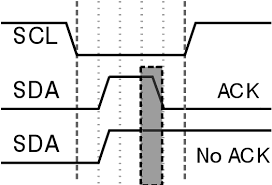
Acknowledge (ACK) and Not Acknowledge (NACK)

  • ACK: Indicates successful receipt of a byte, where the receiver pulls the SDA line low during the acknowledge clock pulse.
  • NACK: Indicates unsuccessful receipt or inability to receive further data, where the SDA line remains high during the acknowledge clock pulse.

Byte Format and Clock Synchronization

Every byte transmitted on the I2C bus contains eight bits, followed by an ACK bit. Data is transmitted with the most significant bit (MSB) first. The master manages clock synchronization and arbitration to handle multiple masters communicating simultaneously.

Advanced Features:

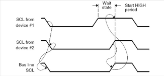
  • Clock Stretching: Slave devices can hold the SCL line low to pause the master, providing additional time to process data. This feature is essential for devices with limited processing power or memory.
  • Addressing and Direction Control: I2C supports both 7-bit and 10-bit addressing modes. During data transfer, the slave address is followed by a direction bit (R/W) that indicates whether the master intends to read or write.

Arbitration and Bus Management

I2C arbitration ensures that when multiple masters try to communicate simultaneously, only one master controls the bus. To manage this, each master monitors the SDA line and yields control if it detects a mismatch between the expected and actual bus state.


Using I2C with Microcontrollers:

Microcontrollers like the Microchip PIC implement I2C through the Master Synchronous Serial Port (MSSP) module. This module supports full master and slave functionality in I2C mode, managing both the SCL and SDA lines and generating interrupts for start and stop conditions to ensure seamless communication.

Key I2C Registers in the MSSP Module:

  • MSSP Control Register 1 (SSPCON1)
  • MSSP Control Register 2 (SSPCON2)
  • MSSP Status Register (SSPSTAT)
  • Serial Receive/Transmit Buffer Register (SSPBUF)
  • MSSP Shift Register (SSPSR) (not directly accessible)
  • MSSP Address Register (SSPADD)

Slave Mode Operation

In Slave mode, the SCL and SDA pins function as inputs. The MSSP module generates interrupts when an address match occurs or when start and stop conditions are detected. Once an address match is found, the data is transferred to SSPBUF, and the BF flag is set. An ACK pulse follows to confirm receipt.

Master Mode Operation

In Master mode, you activate it by configuring SSPCON1’s SSPM bits and enabling SSPEN. The MSSP hardware controls the SCL and SDA lines, and the module automatically handles start and stop conditions. During data transfer, it transmits information through SSPBUF and generates ACK or NACK signals based on the transmission result. The Baud Rate Generator (BRG) regulates SCL frequency, ensuring compliance with I2C specifications.

Project Name: I2C Communication with PIC Microcontroller

This project demonstrates how to configure a PIC microcontroller as an I2C master to communicate with a slave device. It reads data from the slave and displays it on an LED bar connected to Port D. The code manages I2C initialization, communication start/stop sequences, and data transfer to ensure seamless master-slave interaction using the I2C protocol.

Master Side (Key Points)

  • I2C Configuration:

We configure the master with a clock frequency of 16 MHz and a baud rate of 100 kbps using the XC8 compiler.

// CONFIG
#pragma config FOSC = HS    // Oscillator Selection bits (HS oscillator)
#pragma config WDTE = OFF   // Watchdog Timer Enable bit (WDT disabled)
#pragma config PWRTE = OFF  // Power-up Timer Enable bit (PWRT disabled)
#pragma config BOREN = ON   // Brown-out Reset Enable bit (BOR enabled)
#pragma config LVP = OFF    // Low-Voltage (Single-Supply) In-Circuit Serial Programming Enable bit (RB3 is digital I/O, HV on MCLR must be used for programming)
#pragma config CPD = OFF    // Data EEPROM Memory Code Protection bit (Data EEPROM code protection off)
#pragma config WRT = OFF    // Flash Program Memory Write Enable bits (Write protection off; all program memory may be written to by EECON control)
#pragma config CP = OFF     // Flash Program Memory Code Protection bit (Code protection off)

#include <xc.h>

#define _XTAL_FREQ 16000000      // 16 MHz Clock Frequency
#define I2C_BAUD_RATE 100000     // I2C Baud Rate: 100 Kbps
  • I2C Communication:

We use functions like I2C_Start(), I2C_Stop(), I2C_Write(), and I2C_Read() to initiate communication and transfer data between the master and slave.

void I2C_Master_Init(void) {
    SSPCON = 0x28;              // SSPEN = 1, I2C Master mode
    SSPCON2 = 0x00;
    SSPSTAT = 0x00;
    SSPADD = ((_XTAL_FREQ / 4) / I2C_BAUD_RATE) - 1;  // Baud rate formula
    TRISC3 = 1;                // SCL (clock) as input
    TRISC4 = 1;                // SDA (data) as input
}

void I2C_Wait(void) {
    while ((SSPSTAT & 0x04) || (SSPCON2 & 0x1F));  // Wait until SSPBUF is clear
}

void I2C_Start(void) {
    I2C_Wait();
    SEN = 1;  // Initiate I2C start condition
}

void I2C_Stop(void) {
    I2C_Wait();
    PEN = 1;  // Initiate I2C stop condition
}

void I2C_ACK(void) {
    I2C_Wait();
    ACKDT = 0;  // 0 -> ACK
    ACKEN = 1;  // Send ACK signal
}

void I2C_NACK(void) {
    I2C_Wait();
    ACKDT = 1;  // 1 -> NACK
    ACKEN = 1;  // Send NACK signal
}

unsigned char I2C_Write(unsigned char data) {
    I2C_Wait();
    SSPBUF = data;  // Load data into buffer
    I2C_Wait();
    return ACKSTAT;  // Return ACK/NACK status
}

unsigned char I2C_Read(void) {
    unsigned char data;
    I2C_Wait();
    RCEN = 1;  // Enable receive mode
    I2C_Wait();
    data = SSPBUF;  // Read data from buffer
    I2C_NACK();     // Send NACK signal
    return data;
}
  • Main Function Loop:

The master continuously requests data from the slave, displaying the state of the DIP switch on the LED bar through Port D.

void main(void) {
    // Configure Port D as output for LED bar
    TRISD = 0x00;
    PORTD = 0x00;

    // Initialize I2C master
    I2C_Master_Init();

    while (1) {
        I2C_Start();           // I2C Start Sequence
        I2C_Write(0x41);       // I2C Slave Device Address (0x40) + Read (1)
        PORTD = I2C_Read();    // Read data from slave and display on Port D
        I2C_Stop();            // I2C Stop Sequence
        __delay_ms(100);       // Delay 100 ms
    }
}

Slave Side (Key Points)

  • Main Loop:

The slave waits passively for communication from the master. Upon receiving a read request, it sends the DIP switch state.


// CONFIG
#pragma config FOSC = HS        // Oscillator Selection bits (HS oscillator)
#pragma config WDTE = OFF       // Watchdog Timer Enable bit (WDT disabled)
#pragma config PWRTE = OFF      // Power-up Timer Enable bit (PWRT disabled)
#pragma config BOREN = ON       // Brown-out Reset Enable bit (BOR enabled)
#pragma config LVP = OFF        // Low-Voltage (Single-Supply) In-Circuit Serial Programming Enable bit (RB3 is digital I/O, HV on MCLR must be used for programming)
#pragma config CPD = OFF        // Data EEPROM Memory Code Protection bit (Data EEPROM code protection off)
#pragma config WRT = OFF        // Flash Program Memory Write Enable bits (Write protection off; all program memory may be written to by EECON control)
#pragma config CP = OFF         // Flash Program Memory Code Protection bit (Code protection off)

#include <xc.h>

#define _XTAL_FREQ 4000000   // 4 MHz Clock Frequency

// Function Prototypes
void I2C_Slave_Init(unsigned char address);

void main(void) {
    // Configure Port B as input for DIP switch
    TRISB = 0xFF;
    nRBPU = 0;  // Enable PORTB pull-ups

    // Initialize I2C slave with address 0x40
    I2C_Slave_Init(0x40);

    while (1) {
        // Infinite loop, waiting for I2C communication
    }
}
  • Interrupt-Driven Communication:

The slave handles incoming communication requests through an interrupt service routine (ISR). It reads the DIP switch state and sends this data to the master.

void __interrupt() ISR(void) {
    if (SSPIF) {  // Check if I2C interrupt flag is set
        if (!D_nA && R_nW) {  // Check if it is an address match and read request
            volatile char dummy = SSPBUF;  // Clear the buffer
            SSPBUF = PORTB;  // Load the DIP switch state into the buffer
            CKP = 1;  // Release the clock
            while (BF);  // Wait until the buffer is clear
        }
        CKP = 1;  // Release the clock
        SSPIF = 0;  // Clear the interrupt flag
    }
}
  • I2C Slave Initialization:

The slave is initialized with the address 0x40, using clock stretching to ensure proper synchronization with the master.

void I2C_Slave_Init(unsigned char address) {
    SSPADD = address;  // Set the I2C slave address
    SSPSTAT = 0x80;  // Slew rate control disabled
    SSPCON = 0x36;  // Enable clock stretching and set slave mode
    SSPCON2 = 0x01;  // Enable general call
    TRISC3 = 1;  // Set SCL as input
    TRISC4 = 1;  // Set SDA as input
    GIE = 1;  // Enable global interrupts
    PEIE = 1;  // Enable peripheral interrupts
    SSPIF = 0;  // Clear SSP interrupt flag
    SSPIE = 1;  // Enable SSP (I2C) interrupt
}

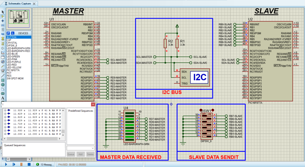
Proteus Configuration :

  • Open Proteus & Create New Project and click next

  • Click on Pick Device
  • Search for PIC16F877A & LED-BARGRAPH-GRN & DIPSW_8
  • Click on Terminal Mode then choose (DEFAULT & POWER &GROUND)
  • finally make the circuit below and start the simulation
PIC16F877 microcontroller circuit diagram for I2C communication in Proteus simulation.

That’s all!

If you have any questions or suggestions don’t hesitate to leave a comment below

You Might Also Like

Leave a Comment


Are you sure want to unlock this post?
Unlock left : 0
Are you sure want to cancel subscription?
-
00:00
00:00
Update Required Flash plugin
-
00:00
00:00