In this project, explore PIC16F877 sensor integration with HIH-5030 humidity and TMP36 temperature sensors for effective environmental monitoring.
Integrating HIH-5030 Humidity and TMP36 Temperature Sensors with PIC16F877 for Precise Environmental Monitoring
In this project, we will explore PIC16F877 Sensor Integration by interfacing the HIH-5030 humidity and TMP36 temperature sensors with the PIC16F877A microcontroller, enabling precise environmental monitoring in embedded systems.
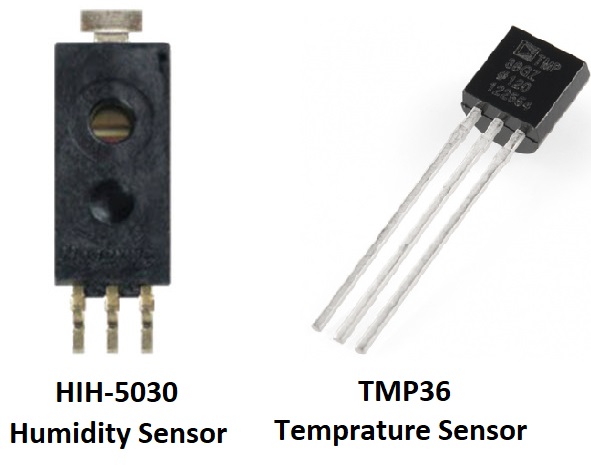
HIH-5030 Humidity Sensor Overview
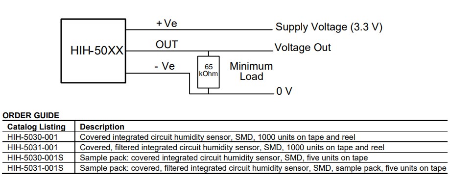
The HIH-5030 Series is a low voltage humidity sensor designed for accurate, reliable humidity measurement in battery-powered systems and various environmental conditions. With a near-linear voltage output, it offers a cost-effective solution for a wide range of applications, from industrial to medical environments.
Core Specifications
- Operating Voltage: 2.7V to 5.5V
- Current Draw: 200 µA (typical)
- Output: Near linear voltage corresponding to relative humidity
- Package Type: Surface Mount Device (SMD)
- Temperature Range: -40°C to +85°C
Accuracy & Performance
- Relative Humidity Accuracy: ±3% (typical)
- Long-term Stability: <3% RH drift over 5 years
- Output Linearity: High linearity voltage output
Key Features
- Low operating voltage, ideal for battery-powered systems
- SMD packaging for automated, high-volume manufacturing
- Excellent sensor interchangeability, reducing calibration costs
- Hydrophobic filter option (HIH-5031) for condensation-resistant applications
- Resistant to dust, dirt, oils, and most environmental hazards
Common Applications
- Industrial: Air compressors, drying equipment, HVAC systems, refrigeration
- Medical: Infant incubators, hospital air compressors, sleep apnea equipment
- Environmental Monitoring: Weather stations, telecommunications cabinets
- Battery-powered Systems: Ideal for portable devices requiring low power consumption
Implementation Benefits
- Suitable for use in a wide range of environments, including condensing conditions
- Excellent resistance to common environmental hazards
- Easy integration with minimal calibration
- Provides accurate, reliable humidity data for embedded systems
TMP36 Temprature Sensor Overview
The TMP36 is a low voltage, precision centigrade temperature sensor that provides a voltage output linearly proportional to the temperature in degrees Celsius. It does not require any external calibration and offers typical accuracy of ±2°C across the temperature range of −40°C to +125°C.
- The TMP36 has a 10 mV/°C output scale factor, meaning for each degree Celsius change in temperature, the output voltage changes by 10 mV. At +25°C, it provides a 750 mV output.
- The sensor is designed to operate from a single supply voltage between 2.7 V and 5.5 V.
- Its low quiescent current (under 50 µA) and shutdown current (0.5 µA max) make it ideal for battery-powered systems, offering minimal self-heating (less than 0.1°C in still air), thus providing high-precision measurements without significantly influencing the environment.
The TMP36 is functionally compatible with other popular temperature sensors like the LM35, and it is often used in temperature monitoring systems that require precise readings, such as in industrial, automotive, or consumer electronics applications.
Package Options
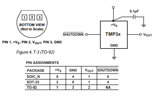
- SOT-23
- SOIC_N
- TO-92 (used in the project)
Shutdown Operation:
- The TMP36 features a shutdown pin that reduces power consumption to under 0.5 µA when not in use.
- The SHUTDOWN pin, controlled by a logic-level signal, turns off the output stage, making it ideal for energy-efficient systems.
- In shutdown mode, the VOUT pin enters a high-impedance state, allowing for external control.
- To keep the sensor active, the SHUTDOWN pin should be tied to +VS.
Thermal Effects:
- Self-heating: The TMP36 has minimal self-heating, with an increase of less than 0.04°C (in SOT-23 package).
- Thermal Response Time: The sensor reaches 63.2% of the final temperature within ~50 seconds in still air, and under 3 seconds when immersed in a stirred oil bath.
FEATURES
- Low voltage operation: 2.7 V to 5.5 V Calibrated directly in °C: No external calibration required
- Output Scale Factor: 10 mV/°C
- Accuracy: ±2°C over temperature range (typical)
- Linearity: ±0.5°C (typical)
- Temperature range: −40°C to +125°C, operation up to +150°C
APPLICATIONS:
- Environmental Control Systems
- Thermal Protection
- Industrial Process Control
- Fire Alarms
- Power System Monitors
- CPU Thermal Managemen
Interfacing the PIC16F877 with an LCD and Sensors (TMP36 Temperature Sensor & Humidity Sensor)
This code demonstrates PIC16F877 Sensor Integration by interfacing a PIC16F877 microcontroller with an LCD and two sensors: a TMP36 temperature sensor and a humidity sensor. Both sensors are connected to the ADC channels of the microcontroller. The program continuously reads the sensor values, averages them, and then displays the temperature and humidity data on the LCD.
Header Files and Constants Declaration
This phase includes the necessary header files and defines constants and global variables used for ADC calculations, sensor readings, and LCD control.
#include "main.h"
#include "lcd.h"
#include <stdio.h>
#include <string.h>

// Constants for ADC calculations
#define V_REF 5.0           // ADC reference voltage
#define ADC_RESOLUTION 1024 // 10-bit ADC resolution (0 to 1023)
#define NUM_READINGS 100    // Number of readings for averaging
#define VSUPPLY 3.3

// Global variables
float Vout;
uint16_t ADC_VALUE;
int correctionFactorRH = 0; // Humidity correction factor (if needed)

// Function prototypes
void configure_ADC(void);
void start_ADC_conversion(void);
void wait_for_conversion(void);
uint16_t read_ADC_result(void);
double readHumidity(void);
double readTemperature(void);
ADC Configuration and Sensor Read Functions
This phase contains the functions to configure the ADC, start conversions, wait for completion, and read values from the humidity and temperature sensors.
// Function to configure the ADC module
void configure_ADC(void) {
    ADCON0 = 0x01; // Turn ADC ON, select AN0 channel, ADC clock = Fosc/8
    ADCON1 = 0x80; // All 8 channels are analog, result is "right-justified"
}

// Function to start ADC conversion
void start_ADC_conversion(void) {
    ADCON0bits.GO_DONE = 1; // Start A/D conversion
}

// Function to wait for ADC conversion to complete
void wait_for_conversion(void) {
    while (ADCON0bits.GO_DONE); // Polling GO_DONE until conversion is complete
}

// Function to read ADC result
uint16_t read_ADC_result(void) {
    uint16_t ADC_result = ((uint16_t)ADRESH << 8) + ADRESL; // Read the right-justified 10-bit result
    return ADC_result;
}

// Function to read humidity sensor value from AN0
double readHumidity(void) {
    double sum = 0.0;

    // Configure ADC to use channel AN0
    ADCON0 &= 0xC7; // Clear previous channel selection bits
    ADCON0 |= (0 << 3); // Select AN0 channel

    // Take multiple readings and average them
    for (int i = 0; i < NUM_READINGS; i++) {
        start_ADC_conversion();  // Start ADC conversion
        wait_for_conversion();   // Wait for conversion to complete
        ADC_VALUE = read_ADC_result(); // Read ADC result
        Vout = ADC_VALUE * V_REF / ADC_RESOLUTION;

        // Calculate the humidity reading
        double humidity_value = (((Vout / VSUPPLY) - 0.1515) / 0.00636) + correctionFactorRH;
        sum += humidity_value;
    }

    // Return the average humidity value
    return sum / NUM_READINGS;
}

// Function to read temperature sensor (TMP36) value from AN1
double readTemperature(void) {
    double sum = 0.0;

    // Configure ADC to use channel AN1
    ADCON0 &= 0xC7; // Clear previous channel selection bits
    ADCON0 |= (1 << 3); // Select AN1 channel

    // Take multiple readings and average them
    for (int i = 0; i < NUM_READINGS; i++) {
        start_ADC_conversion();  // Start ADC conversion
        wait_for_conversion();   // Wait for conversion to complete
        ADC_VALUE = read_ADC_result(); // Read ADC result
        Vout = ADC_VALUE * V_REF / ADC_RESOLUTION;

        // Calculate temperature in Celsius for TMP36
        double temperature_value = (Vout - 0.5) * 100.0;

        sum += temperature_value;
    }

    // Return the average temperature value
    return sum / NUM_READINGS;
}
Main Function to Read and Display Data
This phase handles the initialization of the LCD and ADC, reads the sensor data, formats the values, and displays them on the LCD.
void main(void) {
    // Configure LCD control and data pins as output
    TRISC &= ~(1 << 0 | 1 << 1 | 1 << 2);
    TRISD &= ~(1 << 4 | 1 << 5 | 1 << 6 | 1 << 7);

    lcd_initialize(); // Initialize the LCD
    configure_ADC();  // Configure ADC module

    while (1) {
        // Get the temperature reading from TMP36
        double temperature_value = readTemperature();

        // Format temperature value for display
        char temperature_str[16];
        sprintf(temperature_str,"Temp : %.2f C", temperature_value);

        // Get the humidity reading (averaged from multiple readings)
        double humidity_value = readHumidity();

        // Format humidity value for display
        char humidity_str[16];
        sprintf(humidity_str, "Hum  : %.2f %%", humidity_value);

        // Display temperature on the 1st row
        lcd_command(0x80); // Position cursor at 1st Row, 1st Column
        lcd_string((const unsigned char *)temperature_str, strlen(temperature_str));

        // Display humidity on the 2nd row
        lcd_command(0xC0); // Position cursor at 2nd Row, 1st Column
        lcd_string((const unsigned char *)humidity_str, strlen(humidity_str));
    }
}
Proteus Configuration :
- Open Proteus & Create New Project and click next
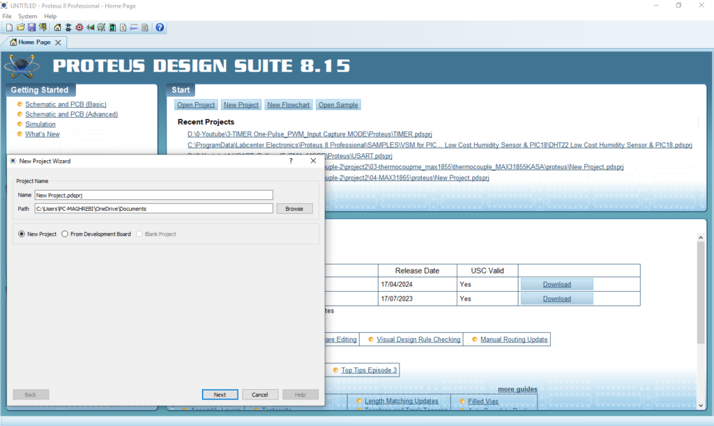
- Click on Pick Device
- Search for PIC16F877A & LCD 12×2 & TMP36 & HIH-5030
- Click on Terminal Mode then choose (DEFAULT & POWER &GROUND)
- finally make the circuit below and start the simulation
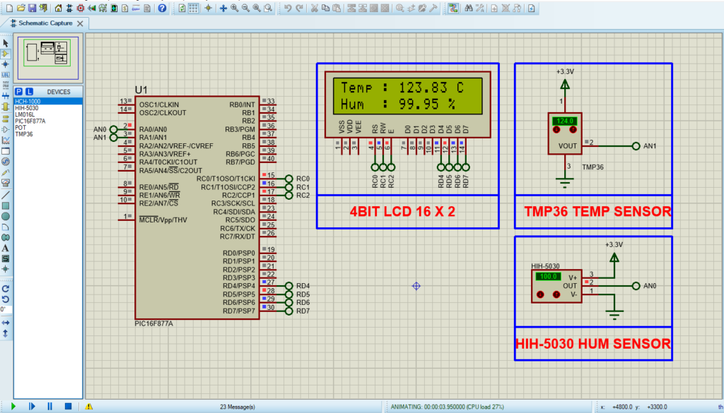
That’s all!
If you have any questions or suggestions don’t hesitate to leave a comment below
