In this article, we explore how to interface the DS18B20 Temperature Sensor with microcontrollers, enabling accurate temperature monitoring for various applications.

Exploring the DS18B20 Temperature Sensor: Interfacing with PIC16F877A for Precise Temperature Measurement
In this project, we will explore how to interface the DS18B20 temperature sensor with a PIC16F877A microcontroller. Temperature sensors like the DS18B20 are essential in a wide variety of applications, from simple environmental monitoring to sophisticated temperature control systems.
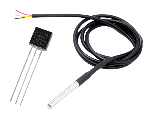
DS18B20 Temperature Sensor Overview
The DS18B20 digital thermometer provides temperature readings in Celsius with a selectable resolution from 9 to 12 bits and features an alarm with user-programmable high and low trigger points stored in nonvolatile memory. It communicates using a 1-Wire bus, which requires only one data line and ground for interfacing with a central microprocessor. The DS18B20 can also operate in “parasite power” mode, drawing power from the data line itself, which removes the need for an external power source.

Each DS18B20 sensor has a unique 64-bit serial code, enabling multiple sensors to operate on the same 1-Wire bus. This makes it straightforward for a single microprocessor to control multiple DS18B20 sensors distributed across a wide area. This capability is especially useful for applications such as HVAC systems, building temperature monitoring, equipment temperature tracking, and process control systems.
For more details on the DS18B20 sensor and its integration with microcontrollers, please refer to the linked article.
Temperature Monitoring with PIC Microcontroller and DS18B20 Sensor
This code sets up a temperature monitoring system using a PIC microcontroller and a DS18B20 temperature sensor. The microcontroller reads temperature data from the DS18B20 sensor, converts it to a readable format, and displays it on an LCD screen. The program is organized to initialize the sensor, configure the LCD for display, and continuously update the temperature every second.
Configuration and Pin Definitions
This part configures the PIC microcontroller’s system settings and defines key pins for the DS18B20 temperature sensor and the LCD control. These definitions simplify access to pins throughout the code and set up necessary system parameters.
#include <xc.h>          // Include PIC microcontroller library
#include <stdio.h>       // For sprintf function
#include <string.h>      // For string operations

#define _XTAL_FREQ 20000000 // Define crystal frequency for delay calculations

// Configuration bits
#pragma config FOSC = HS     // High-speed oscillator
#pragma config WDTE = OFF    // Watchdog Timer disabled
#pragma config PWRTE = OFF   // Power-up Timer disabled
#pragma config BOREN = OFF   // Brown-out Reset disabled
#pragma config LVP = ON      // Low-Voltage Programming enabled
#pragma config CPD = OFF     // Data EEPROM Code Protection disabled
#pragma config WRT = OFF     // Flash Program Memory Write Protection disabled
#pragma config CP = OFF      // Flash Program Memory Code Protection disabled

// DS18B20 Pin definition
#define DS18B20_PIN PORTBbits.RB1
#define DS18B20_TRIS TRISBbits.TRISB1

// LCD control pins
#define RS PORTCbits.RC0
#define RW PORTCbits.RC1
#define EN PORTCbits.RC2
Global Variables and Function Prototypes
This section includes global variables for storing raw and processed temperature data, as well as function prototypes for the LCD and DS18B20 functions. The function prototypes help with modular code structure, keeping the main program flow clear.
// Global variables for temperature
static signed int raw_temp;   // Stores raw temperature data from sensor
static float temperature;     // Stores calculated temperature
static char temp_str[16];     // Buffer for temperature string

// Function prototypes for LCD
void lcd_initialize(void);
void lcd_data(unsigned char data);
void lcd_string(const char *str, unsigned char len);
void lcd_command(unsigned char cmd);

// Function prototypes for DS18B20
unsigned char ds18b20_start(void);
void ds18b20_write_bit(unsigned char bit);
void ds18b20_write_byte(unsigned char byte);
unsigned char ds18b20_read_bit(void);
unsigned char ds18b20_read_byte(void);
unsigned char ds18b20_read(signed int *raw_temp);
Main Program Logic
The main loop initializes the LCD and DS18B20, reads the temperature data from the sensor, converts it to Celsius, and displays the result on the LCD. If the sensor read fails, an error message is displayed instead.
void main(void) {
    // Initialize LCD pins
    TRISCbits.TRISC0 = 0;
    TRISCbits.TRISC1 = 0;
    TRISCbits.TRISC2 = 0;

    TRISDbits.TRISD4 = 0;
    TRISDbits.TRISD5 = 0;
    TRISDbits.TRISD6 = 0;
    TRISDbits.TRISD7 = 0;

    // Initialize DS18B20 pin as input
    DS18B20_TRIS = 1;

    lcd_initialize();

    while(1) {
        if(ds18b20_read(&raw_temp)) {
            // Convert raw value to temperature in Celsius
            temperature = (float)raw_temp * 0.0625;

            // Format temperature as a string
            sprintf(temp_str, "Temp: %2.1f C", temperature);

            // Display temperature on LCD
            lcd_command(0x80);         // Set LCD cursor position
            lcd_string(temp_str, 16);  // Display temperature string
        } else {
            lcd_command(0x80);
            lcd_string("Sensor Error!", 12);  // Display error message
        }
        __delay_ms(1000);  // Update every second
    }
}
DS18B20 Sensor Functions
This part defines the functions needed to communicate with the DS18B20 sensor, including functions to start communication, write and read bits, and read temperature data. Each function manages specific steps in the one-wire protocol required by DS18B20.
// Start DS18B20 communication and check response
unsigned char ds18b20_start(void) {
    unsigned char response;

    DS18B20_TRIS = 0;      // Set as output
    DS18B20_PIN = 0;       // Send reset pulse
    __delay_us(500);       // Hold for 500us

    DS18B20_TRIS = 1;      // Set as input
    __delay_us(100);       // Wait for response

    response = DS18B20_PIN; // Read response
    __delay_us(400);        // Wait 400us

    return !response;       // Return TRUE if sensor detected
}

// Write a single bit to DS18B20
void ds18b20_write_bit(unsigned char bit) {
    DS18B20_TRIS = 0;      // Set as output
    DS18B20_PIN = 0;       // Pull low
    __delay_us(2);

    if(bit) DS18B20_PIN = 1;  // Send bit
    __delay_us(80);        // Hold for 80us

    DS18B20_TRIS = 1;      // Release line
    __delay_us(2);
}

// Write a byte to DS18B20
void ds18b20_write_byte(unsigned char byte) {
    for(unsigned char i = 0; i < 8; i++) {
        ds18b20_write_bit(byte & 0x01);
        byte >>= 1;
    }
}

// Read a single bit from DS18B20
unsigned char ds18b20_read_bit(void) {
    unsigned char bit;

    DS18B20_TRIS = 0;      // Set as output
    DS18B20_PIN = 0;       // Pull low
    __delay_us(2);

    DS18B20_TRIS = 1;      // Release line
    __delay_us(5);         // Wait 5us

    bit = DS18B20_PIN;     // Read bit
    __delay_us(100);       // Wait 100us

    return bit;
}

// Read a byte from DS18B20
unsigned char ds18b20_read_byte(void) {
    unsigned char byte = 0;
    for(unsigned char i = 0; i < 8; i++) {
        byte >>= 1;
        if(ds18b20_read_bit()) byte |= 0x80;
    }
    return byte;
}

// Read temperature from DS18B20
unsigned char ds18b20_read(signed int *raw_temp_value) {
    unsigned char temp_l, temp_h;

    if(!ds18b20_start()) return 0;

    ds18b20_write_byte(0xCC);  // Skip ROM command
    ds18b20_write_byte(0x44);  // Start conversion

    while(!ds18b20_read_byte());  // Wait for conversion

    if(!ds18b20_start()) return 0;

    ds18b20_write_byte(0xCC);  // Skip ROM command
    ds18b20_write_byte(0xBE);  // Read scratchpad

    temp_l = ds18b20_read_byte();  // LSB
    temp_h = ds18b20_read_byte();  // MSB

    *raw_temp_value = (temp_h << 8) | temp_l;

    return 1;
}
LCD Display Functions
This section contains the LCD functions to initialize the display, send commands, and display data. These functions handle LCD control for clear and formatted temperature display.
// Initialize LCD for 4-bit mode
void lcd_initialize(void) {
    lcd_command(0x02); // Return cursor to home position
    lcd_command(0x28); // Set 4-bit mode, 2-line display, 5x8 font
    lcd_command(0x06); // Set entry mode with auto-increment
    lcd_command(0x0C); // Display ON, cursor OFF
    lcd_command(0x01); // Clear display
    __delay_ms(2);     // Short delay for clear screen command
}

// Send data to LCD
void lcd_data(unsigned char data) {
    RS = 1; RW = 0;       // Set to data mode and write
    PORTD = (data & 0xF0); // Send upper nibble
    EN = 1;
    __delay_ms(2);
    EN = 0;

    PORTD = ((data << 4) & 0xF0); // Send lower nibble
    EN = 1;
    __delay_ms(2);
    EN = 0;
}

// Send string to LCD
void lcd_string(const char *str, unsigned char len) {
    for(unsigned char i = 0; i < len; i++) {
        lcd_data(str[i]);
    }
}

// Send command to LCD
void lcd_command(unsigned char cmd) {
    RS = 0; RW = 0;       // Set to command mode and write
    PORTD = (cmd & 0xF0); // Send upper nibble
    EN = 1;
    __delay_ms(2);
    EN = 0;

    PORTD = ((cmd << 4) & 0xF0); // Send lower nibble
    EN = 1;
    __delay_ms(2);
    EN = 0;
}
Proteus Configuration :
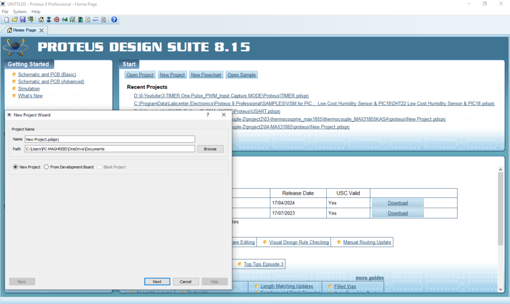
- Open Proteus & Create New Project and click next

- Click on Pick Device
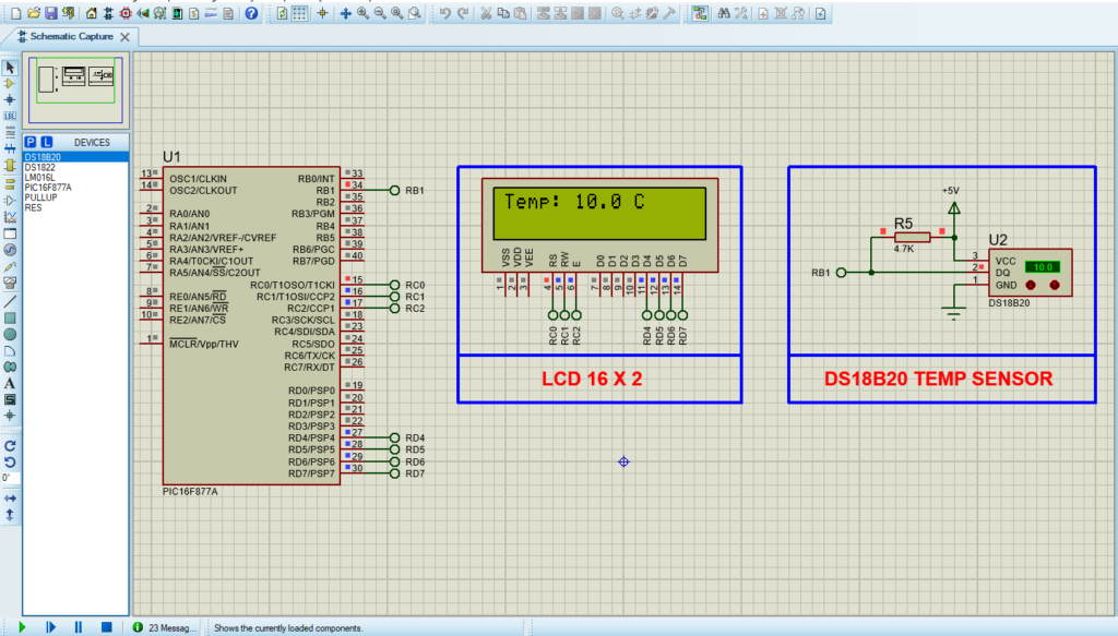
- Search for PIC16F877A & DS18B20 & RESISTANCE
- Click on Terminal Mode then choose (DEFAULT & POWER &GROUND)
- finally make the circuit below and start the simulation

That’s all!
If you have any questions or suggestions don’t hesitate to leave a comment below
