In this article, we’ll explore how to interface the DS1620 digital thermometer with the PIC16F877A microcontroller for precise temperature measurement.

Interfacing the DS1620 Digital Thermometer with the PIC16F877A Microcontroller

DS1620 Temperature Sensor Overview
he DS1620 is a 9-bit digital thermometer with a bandgap-based sensor, measuring temperatures from -55°C to +125°C in 0.5°C increments. It features a 3-wire serial interface and provides thermal alarm outputs (THIGH, TLOW, and TCOM) for thermostat functionality. These outputs allow the DS1620 to monitor temperature thresholds and enable temperature control in various applications.
Features
- Conversion Time: Converts temperature to a digital word within a maximum of 750ms.
- Power Supply Range: Operates with a supply voltage ranging from 2.7V to 5.5V.
- Compact and Efficient: No external components required; available in 8-Pin DIP or SOIC (208-mil) packages.
Pin Description
- DQ: 3-Wire Input/Output
- CLK/CONV: 3-Wire Clock Input and Stand-alone Convert Input
- RST: 3-Wire Reset Input
- GND: Ground
- THIGH: High Temperature Trigger
- TLOW: Low Temperature Trigger
- TCOM: High/Low Combination Trigger
- VDD: Power Supply Voltage (3V – 5V)

Applications
- Thermostatic controls
- Industrial systems
- Consumer products
- Thermometers
DS1620 Functional Block Diagram
The DS1620 utilizes a bandgap-based temperature sensor to provide temperature readings in a 9-bit, two’s complement format. Temperature data is transmitted serially via a 3-wire interface, with the Least Significant Bit (LSB) transmitted first. The sensor measures temperature over a range of –55°C to +125°C with 0.5°C increments.
Data can be read or written as a 9-bit word or in two 8-bit transfers, with the most significant 7 bits ignored. Temperature is represented with a ½°C LSB, resulting in the 9-bit format.

DS1620 Thermostat Operation Controls
The DS1620 features three thermally triggered outputs—THIGH, TLOW, and TCOM—that enable thermostat functionality. THIGH activates when the temperature exceeds the high threshold, TLOW activates when the temperature falls below the low threshold, and TCOM remains high between the high and low thresholds, providing hysteresis. These outputs can be used to control cooling or heating systems in closed-loop applications, maintaining temperature within desired ranges.
DS1620 Operation and Control Overview
The DS1620 requires temperature settings in the TH and TL registers for thermostatic operation. The configuration/status register controls its operation mode and shows the status of the temperature conversion.

Important flags include DONE (conversion status), THF and TLF (temperature threshold flags), and NVB (nonvolatile memory busy). The CPU bit configures the CLK/CONV pin for either standalone mode or CPU communication over the 3-wire interface.
OPERATION IN STAND-ALONE MODE
In stand-alone mode, the DS1620 functions as a thermostat without requiring a CPU. Temperature conversions can be triggered using the CLK/CONV pin, and the CPU bit must be set to 0 for this mode to be enabled.
3-WIRE COMMUNICATIONS
The DS1620 uses a 3-wire interface for data communication, consisting of RST, CLK, and DQ signals. Data transfers are initiated by driving the RST pin high, with the DQ pin outputting data on the falling edge of the clock
Temperature Monitoring System with PIC Microcontroller and DS1620 Sensor
This project uses a PIC microcontroller and DS1620 sensor to monitor temperature. The temperature is read, converted, and displayed on an LCD every second. It utilizes bit-banging to communicate with the sensor and provides temperature readings with 0.5°C resolution. The code configures the necessary peripherals for operation.
Includes and Configuration
This section includes necessary header files and defines configuration bits and control pins for the LCD and DS1620 sensor. The configuration bits set various features of the microcontroller, such as oscillator, watchdog timer, and low-voltage programming. Pin definitions for controlling the LCD and DS1620 sensor are also provided.
#include <xc.h>
#include <stdio.h>
#include <string.h>

#define _XTAL_FREQ 20000000

// Configuration bits
#pragma config FOSC = HS     // High-speed oscillator
#pragma config WDTE = OFF    // Watchdog Timer disabled
#pragma config PWRTE = OFF   // Power-up Timer disabled
#pragma config BOREN = OFF   // Brown-out Reset disabled
#pragma config LVP = ON      // Low-Voltage Programming enabled
#pragma config CPD = OFF     // Data EEPROM Code Protection disabled
#pragma config WRT = OFF     // Flash Program Memory Write Protection disabled
#pragma config CP = OFF      // Flash Program Memory Code Protection disabled

// LCD control pins
#define RS PORTCbits.RC3
#define RW PORTCbits.RC4
#define EN PORTCbits.RC5

// DS1620 pins
#define DQ PORTCbits.RC0
#define DQ_TRIS TRISCbits.TRISC0
#define CLK PORTCbits.RC1
#define RST PORTCbits.RC2

// DS1620 Commands
#define START_CONVERT  0xEE
#define STOP_CONVERT   0x22
#define READ_TEMP      0xAA
#define WRITE_CONFIG   0x0C
#define READ_CONFIG    0xAC

// Global variables
static char temp_str[16];
Function Prototypes and DS1620 Communication Functions
This section defines the function prototypes and implementations for handling the DS1620 sensor communication, including reading and writing data to the sensor. It also includes the functions for initiating the sensor, controlling the sensor’s clock, and ending the data transfer. These functions handle the low-level protocol for interfacing with the DS1620.
// Function prototypes
void lcd_initialize(void);
void lcd_data(unsigned char data);
void lcd_string(const char *str, unsigned char len);
void lcd_command(unsigned char cmd);
void write_data(unsigned char data);
unsigned int read_data(void);
void start_transfer(void);
void end_transfer(void);
void ds1620_init(void);
signed int read_temperature(void);

// DS1620 Functions
void write_data(unsigned char data) {
    unsigned char i;
    DQ_TRIS = 0;  // Set DQ as output

    for(i = 0; i < 8; i++) {
        CLK = 0;
        DQ = (data >> i) & 0x01;  // LSB first
        CLK = 1;
        __delay_us(1);
    }
}

unsigned int read_data(void) {
    unsigned char i;
    unsigned int data = 0;

    DQ_TRIS = 1;  // Set DQ as input

    for(i = 0; i < 9; i++) {  // Read 9 bits for temperature
        CLK = 0;
        __delay_us(1);
        data |= ((unsigned int)(DQ) << i);  // LSB first
        CLK = 1;
        __delay_us(1);
    }

    DQ_TRIS = 0;  // Set back to output
    return data;
}

void start_transfer(void) {
    CLK = 0;
    RST = 1;
    __delay_us(1);
}

void end_transfer(void) {
    RST = 0;
    __delay_us(1);
}

void ds1620_init(void) {
    // Configure DS1620
    start_transfer();
    write_data(WRITE_CONFIG);
    write_data(0x02);  // CPU mode, continuous conversion
    end_transfer();
    __delay_ms(50);    // Allow time for writing to config register

    // Start continuous conversion
    start_transfer();
    write_data(START_CONVERT);
    end_transfer();
    __delay_ms(750);   // Maximum conversion time
}

signed int read_temperature(void) {
    unsigned int raw_temp;

    start_transfer();
    write_data(READ_TEMP);
    raw_temp = read_data();
    end_transfer();

    // Check if the 9th bit is set for two's complement
    if (raw_temp & 0x100) {  // 0x100 is 9th bit in 9-bit number
        raw_temp |= ~0x1FF;  // Sign-extend for two's complement
    }

    return raw_temp;  // Now return the correct signed value
}
LCD Functions
This section defines functions for controlling the LCD display. Functions include initializing the LCD, sending commands and data, and displaying strings on the LCD. The functions use a 4-bit mode to communicate with the LCD.
// LCD Functions
void lcd_initialize(void) {
    __delay_ms(15);    // Wait for LCD to power up

    // Initialize in 4-bit mode
    lcd_command(0x03);
    __delay_ms(5);
    lcd_command(0x03);
    __delay_us(150);
    lcd_command(0x03);
    lcd_command(0x02);

    lcd_command(0x28); // 4-bit mode, 2 lines, 5x8 font
    lcd_command(0x0C); // Display ON, cursor OFF
    lcd_command(0x06); // Auto-increment cursor
    lcd_command(0x01); // Clear display
    __delay_ms(2);     // Clear display command needs longer delay
}

void lcd_data(unsigned char data) {
    RS = 1;
    RW = 0;

    // Send upper nibble
    PORTD &= 0x0F;
    PORTD |= (data & 0xF0);
    EN = 1;
    __delay_us(1);
    EN = 0;
    __delay_us(100);

    // Send lower nibble
    PORTD &= 0x0F;
    PORTD |= ((data << 4) & 0xF0);
    EN = 1;
    __delay_us(1);
    EN = 0;
    __delay_us(100);
}

void lcd_string(const char *str, unsigned char len) {
    for (unsigned char i = 0; i < len; i++) {
        lcd_data(str[i]);
    }
}

void lcd_command(unsigned char cmd) {
    RS = 0;
    RW = 0;

    // Send upper nibble
    PORTD &= 0x0F;
    PORTD |= (cmd & 0xF0);
    EN = 1;
    __delay_us(1);
    EN = 0;
    __delay_us(100);

    // Send lower nibble
    PORTD &= 0x0F;
    PORTD |= ((cmd << 4) & 0xF0);
    EN = 1;
    __delay_us(1);
    EN = 0;
    __delay_us(100);
}
Main Function
This is the main program execution loop. It initializes the microcontroller pins, sets up the LCD and DS1620 sensor, and continuously reads the temperature from the DS1620 sensor. The temperature is displayed on the LCD with 0.5°C resolution.
void main(void) {
    signed int temperature;

    // Initialize pins
    TRISCbits.TRISC1 = 0;  // CLK
    TRISCbits.TRISC2 = 0;  // RST
    TRISCbits.TRISC3 = 0;  // LCD RS
    TRISCbits.TRISC4 = 0;  // LCD RW
    TRISCbits.TRISC5 = 0;  // LCD EN

    // Set D4-D7 as outputs for LCD
    TRISD &= 0x0F;
    PORTD &= 0x0F;

    // Initial states
    CLK = 0;
    RST = 0;

    __delay_ms(100);  // Power-up delay

    // Initialize LCD
    lcd_initialize();

    // Initialize DS1620
    ds1620_init();

    // Display "DS1620 SENSOR" on the first row
    lcd_command(0x80);  // Move cursor to the first row, first column
    lcd_string("DS1620 SENSOR", 13);  // Display text "DS1620 SENSOR"

    // Main loop
    while(1) {
        // Read temperature
        temperature = read_temperature();

        // Convert temperature to string with proper formatting
        sprintf(temp_str, "Temp: %d.%dC",
                temperature / 2,           // Integer part
                (temperature & 1) ? 5 : 0  // Decimal part (0.5 resolution)
        );

        // Display temperature on the second row
        lcd_command(0xC0);  // Move cursor to the second row, first column
        lcd_string(temp_str, strlen(temp_str));

        __delay_ms(1000);  // Update every second
    }
}
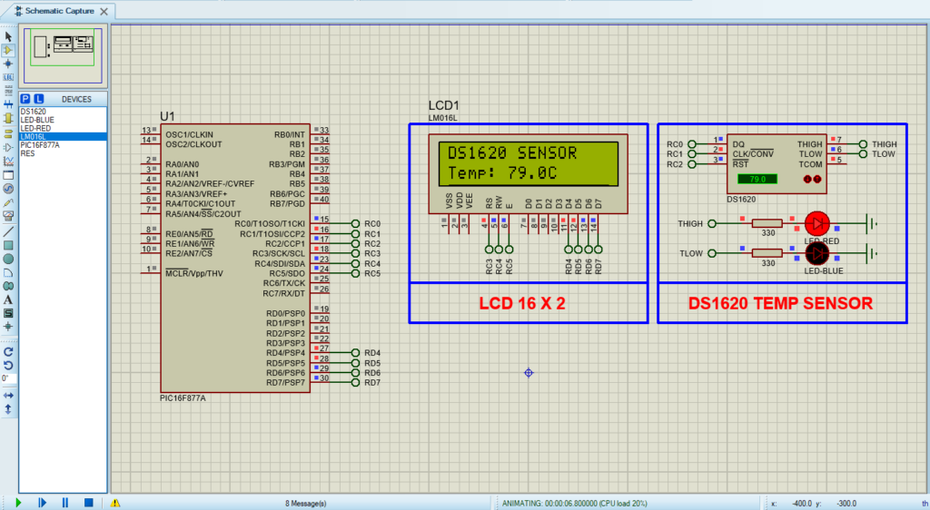
Proteus Configuration :
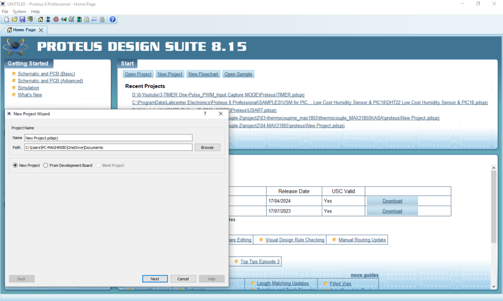
- Open Proteus & Create New Project and click next

- Click on Pick Device
Search for PIC16F877A & DS1620 & RESISTANCE & LCD 16X2 & RED–LED
- Click on Terminal Mode then choose (DEFAULT & POWER &GROUND)
- finally make the circuit below and start the simulation

That’s all!
If you have any questions or suggestions don’t hesitate to leave a comment below
