In this article, we will explore how to interface the DHT11 Temperature and Humidity Sensor with the PIC16F877A microcontroller to measure accurate temperature and humidity readings in your embedded project

Interfacing DHT11 Temperature and Humidity Sensor with PIC Microcontroller
In this project, we will explore how to interface the DHT11 temperature and humidity sensor with a PIC16F877A microcontroller. Temperature and humidity sensors play a crucial role in a wide range of applications, from basic environmental monitoring to advanced climate control systems.
DHT11 Temperature and Humidity Sensor Overview
The DHT11 Temperature & Humidity Sensor is a compact, reliable device designed for measuring temperature and humidity. It features a calibrated digital signal output, utilizing a resistive humidity sensor and an NTC temperature sensor. The sensor operates with an 8-bit microcontroller, ensuring fast response times, strong anti-interference, and excellent long-term stability. Its small size, low power consumption, and single-wire communication interface make it ideal for a variety of applications, including those requiring up to 20 meters of signal transmission.
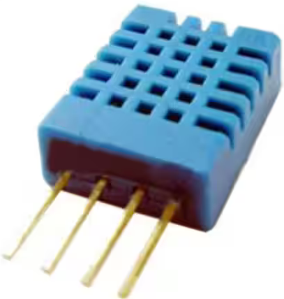
The sensor operates with a power supply of 3-5.5V DC and communicates via a single-wire protocol that transmits data in a 40-bit format, including both temperature and humidity readings along with a checksum for data verification. Calibration coefficients are stored in OTP memory, ensuring high accuracy, particularly in humidity measurement. For stable operation, it is recommended to use a 100nF capacitor between the power and ground pins. The sensor’s simple interface and low power requirements make it a cost-effective solution for embedded systems and environmental monitoring.
For more information about the DHT11 sensor and its integration with microcontrollers, you can refer to the linked article.
DHT11 Temperature and Humidity Monitoring System with PIC16F877A
This project demonstrates how to interface the DHT11 sensor with a PIC16F877A microcontroller to measure both temperature and humidity. The microcontroller reads the data from the DHT11 sensor using precise timing to detect high and low pulses, processes the data, and displays the temperature and humidity values over UART.
Configuration and Initialization
This section configures the microcontroller’s ports, sets up Timer1 for precise timing required for reading the DHT11 sensor, and initializes UART communication to display the readings. The configuration bits are set for the PIC16F877A, including the oscillator type and disabling unnecessary peripherals
#include <xc.h>
#include <stdio.h>
#include "uart.h"

// Configuration bits
#pragma config FOSC = HS        // High Speed Crystal
#pragma config WDTE = OFF       // Watchdog Timer disabled
#pragma config PWRTE = ON       // Power-up Timer enabled
#pragma config BOREN = ON       // Brown-out Reset enabled
#pragma config LVP = OFF        // Low Voltage Programming disabled
#pragma config CPD = OFF        // Data EEPROM Memory Code Protection disabled
#pragma config WRT = OFF        // Flash Program Memory Write disabled
#pragma config CP = OFF         // Flash Program Memory Code Protection disabled

#define _XTAL_FREQ 8000000     // 8MHz Crystal

// DHT11 pin definitions
#define DHT11_PIN      RB0
#define DHT11_PIN_DIR  TRISB0

// Global variables
char Temperature[] = "Temp = 00.0 C";
char Humidity[]    = "RH   = 00.0 %";
unsigned char T_Byte1, T_Byte2, RH_Byte1, RH_Byte2, CheckSum;
Sending Start Signal and Checking Response
To start the data reading process, the microcontroller sends a start signal by pulling the DHT11 data line low for 25ms and then releasing it. The Check_Response function verifies the sensor’s response by measuring the time it takes for the data line to go high and low, ensuring that the sensor is ready to transmit data.
// Send start signal to the sensor
void Start_Signal(void) {
    DHT11_PIN_DIR = 0;     // Configure as output
    DHT11_PIN = 0;         // Pull data line low
    __delay_ms(25);        // Wait 25ms
    DHT11_PIN = 1;         // Release data line
    __delay_us(30);        // Wait 30us
    DHT11_PIN_DIR = 1;     // Configure as input
}

// Check sensor response
unsigned char Check_Response(void) {
    TMR1H = 0;                  // Reset Timer1
    TMR1L = 0;
    TMR1ON = 1;                 // Enable Timer1 module

    while(!DHT11_PIN && TMR1L < 100);  // Wait for DHT11_PIN to go high (80s low time)

    if(TMR1L > 99)              // If response time > 99s
        return 0;               // Return 0 (response error)

    TMR1H = 0;                  // Reset Timer1
    TMR1L = 0;

    while(DHT11_PIN && TMR1L < 100);   // Wait for DHT11_PIN to go low (80s high time)

    if(TMR1L > 99)              // If response time > 99s
        return 0;               // Return 0 (response error)

    return 1;                   // Return 1 (response OK)
}
Reading Data from the DHT11 Sensor
The Read_Data function reads 8 bits of data from the sensor by measuring the duration of high and low pulses. It uses Timer1 to measure the time and determine whether the bit is a 1 or 0 based on the duration of the high pulse. The function returns 0 if the data is successfully read, and 1 if a timeout occurs.
// Read data from sensor
unsigned char Read_Data(unsigned char* dht_data) {
    *dht_data = 0;

    for(char i = 0; i < 8; i++) {
        TMR1H = 0;              // Reset Timer1
        TMR1L = 0;

        while(!DHT11_PIN)       // Wait for rising edge
            if(TMR1L > 100)     // Timeout if low time > 100s
                return 1;

        TMR1H = 0;              // Reset Timer1
        TMR1L = 0;

        while(DHT11_PIN)        // Wait for falling edge
            if(TMR1L > 100)     // Timeout if high time > 100s
                return 1;

        if(TMR1L > 50)          // If high time > 50s = bit is 1
            *dht_data |= (1 << (7 - i));
    }

    return 0;                   // Return 0 (data read OK)
}
Main Function: Continuously Read and Display Temperature and Humidity
The main function continuously reads the temperature and humidity from the DHT11 sensor. It sends the start signal, checks for a valid response, reads the data bytes, and calculates the temperature and humidity. If the checksum is valid, it updates the message strings and sends the results over UART. If there is an error in reading or checksum validation, it displays an error message.
void main(void) {
    // Initialize ports
    TRISB = 0b00000001;    // RB0 as input for DHT11
    TRISC = 0b10000000;    // Set RC6 as output for UART TX
    ADCON1 = 0x06;         // Configure PORTA pins as digital I/O

    // Timer1 configuration - 1:2 prescaler (Timer1 clock = 1MHz at 8MHz crystal)
    T1CON = 0x10;
    TMR1H = 0;
    TMR1L = 0;

    // Initialize UART
    UART_TX_Init();
    __delay_ms(1000);      // Initial delay

    while(1) {
        Start_Signal();     // Send start signal

        if(Check_Response()) {  // If sensor responds
            // Read all data bytes
            if(Read_Data(&RH_Byte1) || Read_Data(&RH_Byte2) ||
                    Read_Data(&T_Byte1) || Read_Data(&T_Byte2) ||
                    Read_Data(&CheckSum)) {
                UART_Write_Text("Sensor read timeout!\n\r");
            }
            else {  // If no timeout occurred
                if(CheckSum == ((RH_Byte1 + RH_Byte2 + T_Byte1 + T_Byte2) & 0xFF)) {
                    // Update message strings
                    Temperature[7] = T_Byte1/10 + '0';
                    Temperature[8] = T_Byte1%10 + '0';
                    Temperature[10] = T_Byte2/10 + '0';
                    Humidity[7] = RH_Byte1/10 + '0';
                    Humidity[8] = RH_Byte1%10 + '0';
                    Humidity[10] = RH_Byte2/10 + '0';

                    // Send via UART
                    UART_Write_Text(Temperature);
                    UART_Write_Text("\n\r");
                    UART_Write_Text(Humidity);
                    UART_Write_Text("\n\r");
                }
                else {
                    UART_Write_Text("Checksum Error!\n\r");
                }
            }
        }
        else {
            UART_Write_Text("No response from sensor\n\r");
        }

        TMR1ON = 0;        // Disable Timer1
        __delay_ms(1000);  // Wait 1 second before next reading
    }
}
Proteus Configuration :
- Open Proteus & Create New Project and click next
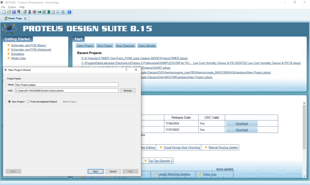
- Click on Pick Device
- Search for PIC16F877A & DHT11 & RESISTANCE
- Click on Virtual Instruments Mode then choose TERMINAL
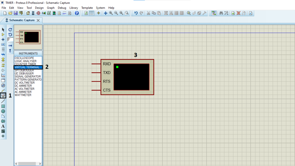
- Click on Terminal Mode then choose (DEFAULT & POWER &GROUND)
- finally make the circuit below and start the simulation
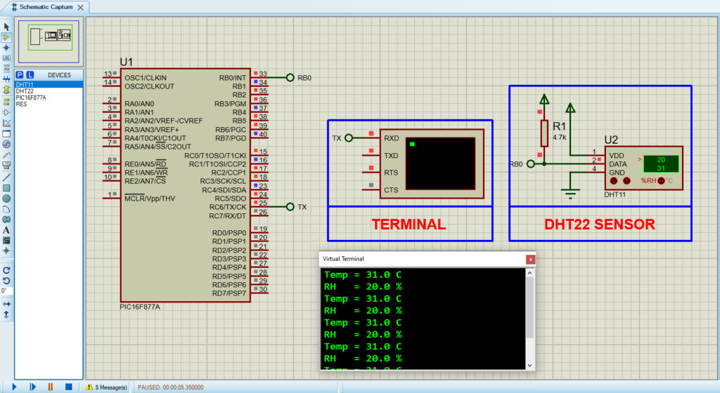
That’s all!
If you have any questions or suggestions don’t hesitate to leave a comment below
