In this article, we’ll examine the PIC16F877 DAC (Digital to Analog Converter) and its importance in microcontroller projects for generating accurate waveforms and converting digital signals to analog.

Understanding Digital-to-Analog Converters (DACs)
In the realm of electronics, the PIC16F877 DAC (Digital-to-Analog Converter) is an essential component that bridges the digital world with the analog domain. By converting digital data (composed of 0s and 1s) into an analog signal, the PIC16F877 DAC enables the generation of continuous analog waveforms from digital information. Functionally, DACs, including the PIC16F877 DAC, perform the inverse operation of analog-to-digital converters (ADCs), and they are significantly more cost-effective.
The Role and Importance of DACs:
The PIC16F877 DAC is ubiquitous in various electronic systems, including audio/music players, video players, televisions, and other devices that require analog signal generation from digital sources

The fundamental need for DACs arises from the digital nature of modern computers, which store, process, and output data in digital form. To interact with the analog world—such as playing back audio or controlling analog actuators—DACs are indispensable.
Applications of DACs:
DACs find applications across a broad spectrum of fields, including but not limited to:
- Audio and Music Players: Converting digital audio files into analog signals for playback.
- Video Players and TVs: Generating analog video signals from digital video data.
- Control Systems: Translating digital control signals into analog voltages for actuators.
- Synthesizers and Waveform Generators: Creating precise analog waveforms.
- Radar and Communication Systems: Converting digital data into analog signals for transmission.
- Instrumentation and Measurement: Generating reference signals for testing and measurement equipment.
Types of DACs:
DACs can be implemented using various techniques, each with its own advantages and limitations:
- Binary Weighted DAC: Uses resistors with binary-weighted values to produce the analog output. This method is fast but requires high precision in resistor values.
- R-2R Ladder DAC: An improvement over binary-weighted DAC, using a repeating structure of resistors valued at R and 2R. This configuration is simpler to implement with matched resistors, offering a good balance between cost and precision.
- PWM DAC: Generates an analog voltage by averaging a high-frequency PWM signal. This method is efficient and easy to implement but requires filtering to obtain a clean output.
- Binary Summing Amplifier DAC: Utilizes an op-amp in a summing configuration with resistors weighted to produce a binary sum. This approach can provide high resolution but may suffer from accuracy issues at higher resolutions.
Using a DAC with Microcontrollers:
Microcontrollers can interface with DACs in various ways depending on the application’s needs:
- R-2R Ladder DAC: An inexpensive and straightforward method to create a DAC using resistors. Ideal for low-cost and simple applications.
- Binary Weighted-Summing DAC: Involves an op-amp in a summing configuration to achieve up to 8-bit resolution. Useful for applications requiring higher precision.
- Serial/Parallel DAC IC: High-precision DAC ICs can be interfaced via serial (SPI) or parallel buses. Suitable for applications demanding high resolution and specific performance characteristics.
- PWM as DAC: Utilizes the microcontroller’s PWM output to generate an analog signal. By varying the duty cycle and filtering the output, a clean DC voltage corresponding to the PWM duty cycle can be obtained.
Project Name: Waveform Generator with PIC16F877A
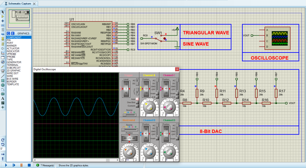
The “Waveform Generator with PIC16F877A” project aims to create versatile waveforms, including sinusoidal and triangular waveforms, using a PIC16F877A microcontroller. By leveraging the microcontroller’s digital-to-analog conversion capabilities and a switch input, this project can dynamically switch between generating sinusoidal and triangular waveforms. When the switch is OFF, the program generates a sinusoidal waveform using predefined lookup tables. Conversely, when the switch is ON, it produces a triangular waveform. The generated waveforms are output through the DAC pin configured as PORTB, enabling visualization using external instrumentation or driving analog components.
Code (in C using XC8 Compiler):
Includes and Configuration
This part includes necessary libraries and defines configuration settings for the PIC microcontroller. It specifies how the microcontroller operates, including oscillator settings, watchdog timer options, and memory protection.
#include <xc.h>
#include <stdint.h>

// CONFIG
#pragma config FOSC = XT        // Oscillator Selection bits (XT oscillator)
#pragma config WDTE = OFF       // Watchdog Timer Enable bit (WDT disabled)
#pragma config PWRTE = OFF      // Power-up Timer Enable bit (PWRT disabled)
#pragma config BOREN = ON       // Brown-out Reset Enable bit (BOR enabled)
#pragma config LVP = OFF        // Low-Voltage (Single-Supply) In-Circuit Serial Programming Enable bit (RB3 is digital I/O, HV on MCLR must be used for programming)
#pragma config CPD = OFF        // Data EEPROM Memory Code Protection bit (Data EEPROM code protection off)
#pragma config WRT = OFF        // Flash Program Memory Write Enable bits (Write protection off; all program memory may be written to by EECON control)
#pragma config CP = OFF         // Flash Program Memory Code Protection bit (Code protection off)
Waveform Lookup Tables
This section defines two lookup tables: one for a sinusoidal wave and another for a triangular wave, each containing 64 samples. These tables will be used to generate the corresponding waveforms.
// Define the sine wave lookup table with 64 samples
uint8_t SineTable[64] = {
    128, 139, 150, 161, 171, 181, 191, 199,
    207, 214, 220, 225, 229, 232, 235, 236,
    237, 236, 235, 232, 229, 225, 220, 214,
    207, 199, 191, 181, 171, 161, 150, 139,
    128, 117, 106, 95, 85, 75, 65, 57,
    49, 42, 36, 31, 27, 24, 21, 20,
    19, 20, 21, 24, 27, 31, 36, 42,
    49, 57, 65, 75, 85, 95, 106, 117
};

// Define the triangular wave lookup table with 64 samples
uint8_t TriangleTable[64] = {
    0, 4, 8, 12, 16, 20, 24, 28,
    32, 36, 40, 44, 48, 52, 56, 60,
    64, 68, 72, 76, 80, 84, 88, 92,
    96, 100, 104, 108, 112, 116, 120, 124,
    128, 132, 136, 140, 144, 148, 152, 156,
    160, 164, 168, 172, 176, 180, 184, 188,
    192, 196, 200, 204, 208, 212, 216, 220,
    224, 228, 232, 236, 240, 244, 248, 252
};
Main Function and Waveform Generation
The main function initializes the ports for output and input, reads the switch state, and continuously generates either a sinusoidal or triangular waveform based on the switch’s state. It outputs the waveform values to the DAC and controls the frequency of the output with a delay.
void main(void) {
    // Configure PORTB as output for DAC
    TRISB = 0x00;

    // Configure RC0 as input for switch
    TRISCbits.TRISC0 = 1;

    // Initialize index variable
    uint8_t i = 0;

    // Initialize switch state variable
    uint8_t switchState = 0;

    // Main loop
    while(1) {
        // Read switch state
        switchState = PORTCbits.RC0;

        // Generate sinusoidal or triangular waveform based on switch state
        if (switchState == 0) {
            // Output the sine wave value to DAC
            DAC_OUT = SineTable[i++];
        } else {
            // Output the triangular wave value to DAC
            DAC_OUT = TriangleTable[i++];
        }

        // Delay for the desired waveform frequency
        __delay_us(390); // Adjust delay for desired frequency

        // Reset index if end of waveform table is reached
        if (i == 64)
            i = 0;
    }

    return;
}
Proteus Configuration :
- Open Proteus & Create New Project and click next

- Click on Pick Device
- Search for PIC16F877A & RES & SWITCH
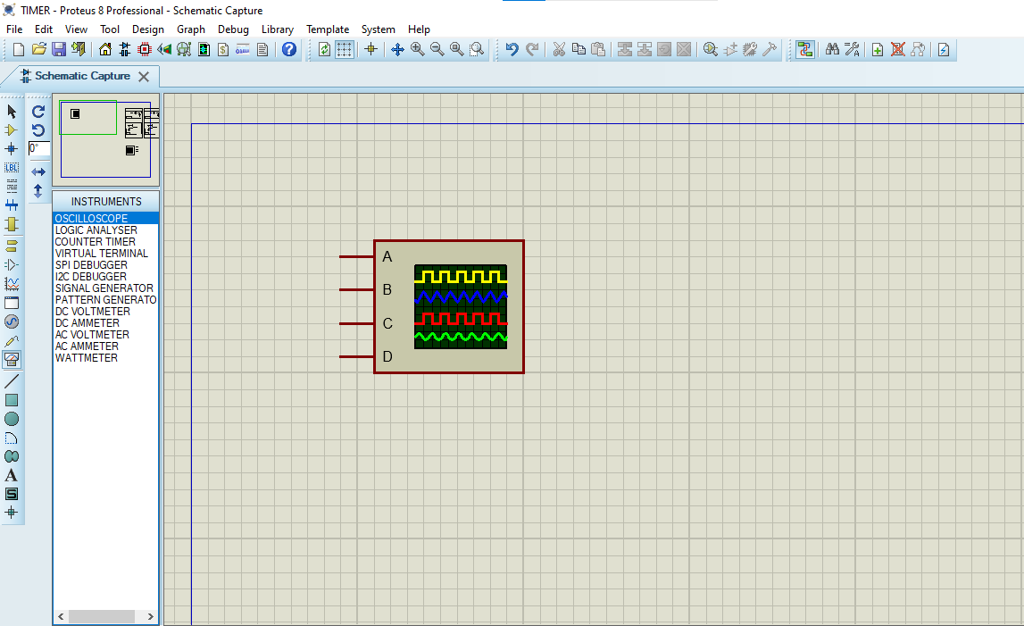
- Click on Virtual Instruments Mode then choose OSCILLOSCOPE

- Click on Terminal Mode then choose (DEFAULT & POWER &GROUND)
- finally make the circuit below and start the simulation

That’s all!
If you have any questions or suggestions don’t hesitate to leave a comment below
