
In this article, we will explore the PIC16F877 Capture and Compare Mode, a crucial feature of the CCP modules that enables precise timing and event handling in embedded systems.

Understanding Capture and Compare Modes in CCP Modules for PIC Microcontrollers
The various modes of (CCP) Capture/Compare/PWM modules, especially within the PIC16F877 Capture and Compare Mode, play a critical role in timing and control applications within embedded systems. The capture mode records the timer value when an external event occurs. This functionality is invaluable for accurately measuring the timing characteristics of external signals, emphasizing the importance of the PIC16F877 Capture and Compare Mode in precise timing applications.
Capture Mode :
In capture mode, the precise timing of external events is recorded by capturing the value of the timer when an event occurs. This mode is particularly beneficial for measuring pulse widths, frequencies, and other timing characteristics of input signals. Furthermore, accurate timing analysis and event synchronization are enabled, which makes it invaluable in applications requiring precision in embedded systems.
Key Features of Capture Mode
- Edge Detection: Capture mode can be configured to trigger on a rising edge, falling edge, or both edges of an incoming signal.
- High-Resolution Measurement: The timer value captured provides a precise measure of the event’s occurrence time.
- Minimal CPU Intervention: The hardware automatically captures the timer value, allowing the CPU to focus on other tasks.
Applications of Capture Mode
- Frequency Measurement: By capturing the time between successive edges of a periodic signal, you can calculate the frequency.
- Pulse Width Measurement: Measure the duration of a high or low pulse by capturing the timer value on both the rising and falling edges.
Compare Mode :
Compare mode generates an output signal when the timer reaches a specified value. This mode is particularly useful for creating precise timing events.
Key Features of Compare Mode
- Programmable Comparison Value: The timer compares against a preset value, triggering an action when they match.
- Various Output Options: The output can toggle, set, clear, or generate a special event trigger.
- Precise Event Generation: This feature is ideal for generating periodic interrupts or controlling output signals at exact intervals.
Applications of Compare Mode
- Generating Square Waves: Toggle an output pin at regular intervals.
- Event Scheduling: Trigger actions or interrupts at specific times.
- Pulse Generation: Create precise pulse trains for communication protocols or other timing-sensitive applications.
In conclusion, CCP modules in capture and compare modes provide essential functionalities for precise timing and control in embedded systems. Capture mode enables accurate measurement of external signals’ timing characteristics, while compare mode facilitates the generation of precise timing events and output control. Understanding and utilizing these modes significantly enhances the capabilities of microcontroller-based projects.
Project1: Capture Mode with LED Toggle
This code configures a PIC microcontroller to operate in capture mode using the CCP1 module. It captures events, compares the captured value, and toggles an LED accordingly. Additionally, it displays the timer value on PORTD and the captured value on PORTB.
Code (in C using XC8 Compiler):
Configuration and Setup
The initial part of the project involves including necessary header files, setting configuration options, and declaring global variables. The configuration dictates how the microcontroller operates, including aspects like the oscillator type and watchdog timer settings. A global variable, captureCount, is initialized to keep track of captured values.
#include <xc.h>
#include <stdint.h>

// Configuration
#pragma config FOSC = XT        // Oscillator Selection bits (XT oscillator)
#pragma config WDTE = OFF       // Watchdog Timer Enable bit (WDT disabled)
#pragma config PWRTE = OFF      // Power-up Timer Enable bit (PWRT disabled)
#pragma config BOREN = ON       // Brown-out Reset Enable bit (BOR enabled)
#pragma config LVP = OFF        // Low-Voltage (Single-Supply) In-Circuit Serial Programming Enable bit (RB3 is digital I/O, HV on MCLR must be used for programming)
#pragma config CPD = OFF        // Data EEPROM Memory Code Protection bit (Data EEPROM code protection off)
#pragma config WRT = OFF        // Flash Program Memory Write Enable bits (Write protection off; all program memory may be written to by EECON control)
#pragma config CP = OFF         // Flash Program Memory Code Protection bit (Code protection off)

// Global variable
uint8_t captureCount = 0;
Interrupt Service Routine (ISR)
The ISR is responsible for handling capture events triggered by the CCP1 module. When an event is captured, the ISR reads the captured value. If this value equals 9, it toggles an LED connected to the microcontroller. Additionally, the captured value is sent to PORTB for display, and the interrupt flag is cleared to allow for future interrupts.
// ISR Handler
void __interrupt() ISR() {
    if (CCP1IF) {
        // Capture event occurred, read CCPR1 value
        uint16_t capturedValue = CCPR1L | (CCPR1H << 8);

        if (capturedValue == 9) {
            // Toggle the LED (now on RC3)
            RC3 = ~RC3;
        }

        // Write CCPR1 value to PORTB
        PORTB = capturedValue;

        // Clear the Interrupt Flag Bit
        CCP1IF = 0;
    }
}
Main Function and Timer Configuration
In the main function, input/output (I/O) ports are configured, and the Timer1 module is set up. The LED connected to pin RC3 is initialized as an output and is turned off initially. Timer1 is configured to operate in counter mode, ensuring it accurately counts events.
// Main function
void main(void) {
    // Configure IO Ports
    TRISC3 = 0; // LED pin (now on RC3) as output
    RC3 = 0;    // Initially OFF

    TRISB = 0x00; // Output Port for Capture Operation (CCPR1 register)
    PORTB = 0x00; // Initial State

    TRISD = 0x00; // Output Port for TMR1 Module (TMR1 register)
    PORTD = 0x00; // Initial State

    // Configure Timer1 Module to Operate in Counter Mode
    TMR1 = 0;
    T1CKPS0 = 0;
    T1CKPS1 = 0;
    TMR1CS = 1; // Counter mode
    T1OSCEN = 1;
    T1SYNC = 0;
    TMR1ON = 1;

    // Configure CCP1 Module to Operate in Capture Mode
    CCP1M0 = 1;
    CCP1M1 = 0;
    CCP1M2 = 1;
    CCP1M3 = 0;

    // Enable CCP1 Interrupt
    CCP1IE = 1;
    PEIE = 1;
    GIE = 1;

    // Main Loop
    while (1) {
        // Read & Print Out the TMR1 Counts
        PORTD = TMR1L;
    }
}
Prject 2 : name Generating a Precise 1Hz Square Wave :
This project aims to use the Compare mode to generate a 1Hz square wave on a pin, which can serve various purposes like clock generation or driving LEDs.
Code (in C using XC8 Compiler):
Configuration and Frequency Settings
The project begins with header files and configuration settings for the microcontroller. It defines constants for frequency settings to calculate the value to load into the CCPR1 register, which will generate a 1Hz square wave based on a 4MHz oscillator frequency.
#include <xc.h>
#include <stdint.h>

// CONFIG
#pragma config FOSC = XT        // Oscillator Selection bits (XT oscillator)
#pragma config WDTE = OFF       // Watchdog Timer Enable bit (WDT disabled)
#pragma config PWRTE = OFF      // Power-up Timer Enable bit (PWRT disabled)
#pragma config BOREN = ON       // Brown-out Reset Enable bit (BOR enabled)
#pragma config LVP = OFF        // Low-Voltage (Single-Supply) In-Circuit Serial Programming Enable bit (RB3 is digital I/O, HV on MCLR must be used for programming)
#pragma config CPD = OFF        // Data EEPROM Memory Code Protection bit (Data EEPROM code protection off)
#pragma config WRT = OFF        // Flash Program Memory Write Enable bits (Write protection off; all program memory may be written to by EECON control)
#pragma config CP = OFF         // Flash Program Memory Code Protection bit (Code protection off)

// Frequency settings for 1Hz square wave
#define _XTAL_FREQ 4000000      // Assuming 4MHz crystal oscillator
#define TIMER1_PRESCALE 1
#define COMPARE_VALUE ((_XTAL_FREQ / (4 * TIMER1_PRESCALE)) - 1) // Calculation for 1 second
Main Function and Initialization
The main function is where I/O ports are configured, specifically the output pin that will generate the square wave. The Compare_Init function is invoked to set up the Timer1 and CCP1 modules to work in compare mode. The main loop remains idle, as the ISR will manage the toggling of the output pin.
// Function prototypes
void Compare_Init();

// Main function
void main(void) {
    // Configure IO Ports
    TRISC4 = 0; // Set The Output Pin For The Square Wave
    RC4 = 0;    // Initially OFF

    // Initialize Compare mode
    Compare_Init();

    // Main Loop
    while (1) {
        // Stay Idle, everything is taken care of in the ISR
    }
}

// Function to initialize Compare mode
void Compare_Init() {
    // Configure Timer1 Module to Operate In Timer Mode
    TMR1 = 0;
    T1CKPS0 = 0;
    T1CKPS1 = 0;
    TMR1CS = 0; // Timer mode
    TMR1ON = 1;

    // Configure CCP1 Module to Operate in Compare Mode
    // Preload The CCPR1 Register with the compare value for 1 second
    CCPR1 = COMPARE_VALUE;
    // CCP in Compare Mode, CCPx Pin Is Unchanged & Trigger Special Event
    CCP1M0 = 1;
    CCP1M1 = 1;
    CCP1M2 = 0;
    CCP1M3 = 1;

    // Enable CCP1 Interrupt
    CCP1IE = 1;
    PEIE = 1;
    GIE = 1;
}
Interrupt Service Routine (ISR)
The ISR for the CCP1 module toggles the output pin RC4 when a compare match occurs (i.e., when Timer1 reaches the compare value set in CCPR1). The interrupt flag is cleared to prepare for the next interrupt, and Timer1 is reset to ensure continuous operation.
// Interrupt Service Routine for CCP1
void __interrupt() ISR() {
    if (CCP1IF) {
        // Toggle The Output Pin to generate a square wave
        RC4 = ~RC4;

        // Clear The Interrupt Flag Bit
        CCP1IF = 0;

        // Reset the Timer1 value
        TMR1 = 0;
    }
}
Proteus Configuration :
- Open Proteus & Create New Project and click next

- Click on Pick Device
- Search for PIC16F877A & 4511 & LEDs & LOGICPROB BIG & 7SEG & BUTTON
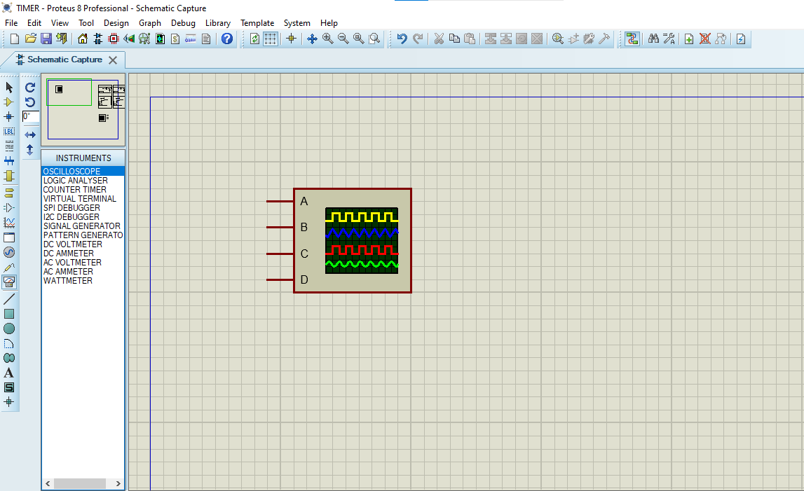
- Click on Virtual Instruments Mode then choose & OSCILLOSCOPE
- Click on Terminal Mode then choose (DEFAULT & POWER &GROUND)
- finally make the circuit below and start the simulation
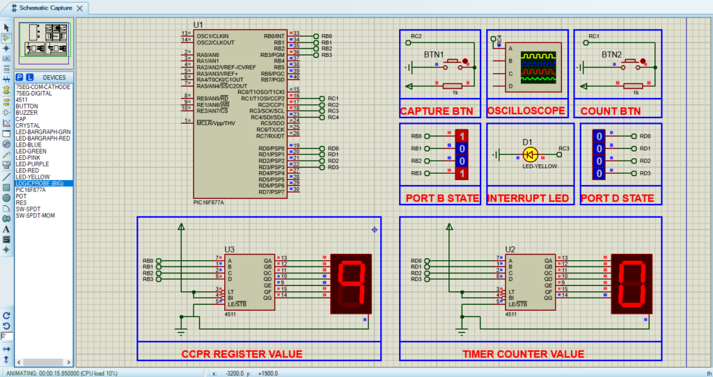
That’s all!
If you have any questions or suggestions don’t hesitate to leave a comment below