PIC16F877 ADC: Complete Guide to Analog to Digital Conversion

by Marwen Maghrebi

In this article, we’ll explore the PIC16F877 ADC, a crucial component for converting analog signals to digital values in microcontroller projects.

Features of the PIC16F877 ADC project.

Things used in this project

Software apps and online services:

1- MPLAB

2- Proteus 8

Understanding Analog to Digital Conversion

PIC16F877 ADC is a critical component in modern electronics, enabling the transformation of analog signals—such as those from microphones or sensors—into digital data that computers and digital signal processors (DSPs)  can handle. This process is facilitated by the PIC16F877 ADC, an essential feature of the PIC16F877 microcontroller designed specifically for this purpose.

In the realm of the PIC16F877 ADC, various configurations are available, each employing different methodologies and offering different performance levels. Typically, the cost of an ADC unit, including the PIC16F877 ADC, corresponds to its accuracy and efficiency in converting signals.

The Importance of Analog to Digital Converters:

The necessity of ADCs arises from the digital nature of computers. While analog signals vary continuously, computers operate on digital data. Many real-world signals, including temperature variations and sound waves, are inherently analog. ADCs bridge this gap by converting these analog signals into digital data, making them compatible with computers.

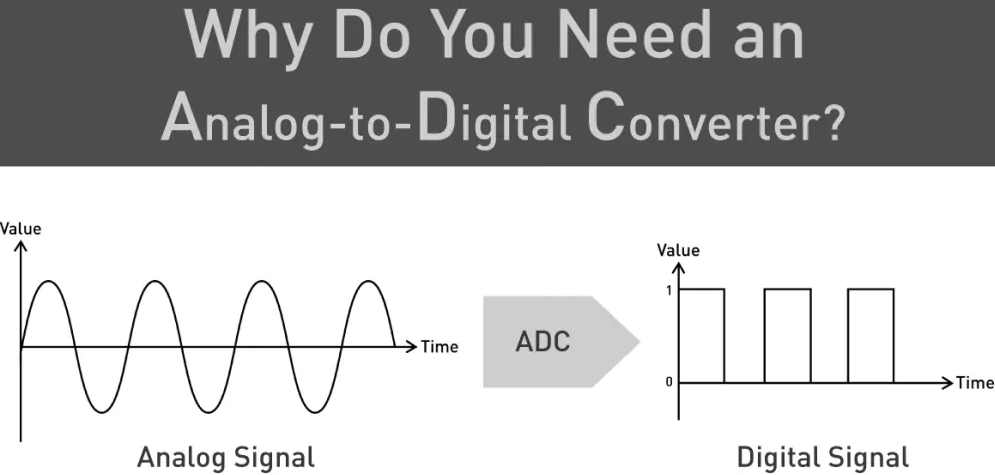
Various electronic sensors—such as temperature sensors, microphones, and pressure sensors—generate analog signals. ADCs convert these signals into digital values, enabling computational manipulation and real-time monitoring or control.

Understanding ADC Operation:

At its core, an ADC consists of a Sample & Hold (S/H) circuit followed by a quantization stage, which performs the actual conversion of analog values into digital data. The type of ADC employed depends on the quantization method, which can include:

  • Analog Integration
  • Digital Counting
  • Successive Approximation
  • Direct Conversion (Flash ADCs)

The resulting digital output data can be sent to the CPU or directly stored in memory. ADCs may be integrated within a microcontroller unit (MCU) or exist as standalone integrated circuits interfaced with a microcontroller’s serial or parallel ports.

Essential Components for ADC Operation:

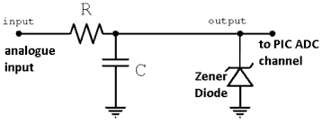
Analog-to-Digital Conversion relies on a stable voltage reference (Vref+) and its counterpart (Vref–), which set the maximum allowable voltage range for accurate conversion. Ensuring a stable Vref is critical for reliable ADC operation. Techniques to maintain a stable voltage reference, despite power supply fluctuations, include using resistors, capacitors, or Zener diodes.

Sampling and Resolution:

The sampling rate, defined as the frequency at which an ADC converts analog signals to digital data, is crucial for preserving signal integrity. The Shannon-Nyquist sampling theorem establishes that to accurately reconstruct an analog signal, the sampling frequency (Fs) must be at least twice the maximum frequency component of the analog signal (FMAX).

Furthermore, oversampling—sampling at a higher rate than necessary and then filtering digitally—can enhance accuracy, particularly in audio ADC applications.

ADC Resolution and Quantization:

Resolution denotes the number of discrete values an ADC can produce over the range of analog values, influencing the maximum achievable signal-to-noise ratio. Resolution is determined by the number of bits (n) and the full-scale range (FSR) of the analog reference voltage..

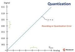
Quantization, performed by the quantizer circuit, converts analog voltages into corresponding digital values. Quantization error, an inevitable consequence of the discrete nature of digital values, affects the accuracy of ADCs.

Types of ADC
ADCs come in various types, each employing different techniques for analog signal quantization. Common types include:

ADC Module in PIC Microcontrollers:

In PIC16F microcontrollers, the ADC module facilitates analog-to-digital conversion. It features multiple channels, selectable voltage references, and operates even in Sleep mode. Configurable through Special Function Registers (SFRs), the ADC module enables developers to interface efficiently with analog sensors.

Project Name: Analog to Digital Converter LED Control

The objective of this project is to control four LEDs using the PIC16F877A microcontroller based on the input from an analog sensor. This project demonstrates the use of the ADC module to read an analog signal, convert it to a digital value, and then control the state of the LEDs accordingly. Each LED represents a different threshold of the analog input, providing a visual indication of the sensor’s output.

Code (in C using XC8 Compiler):

Includes and Configuration

The code begins by including necessary header files that provide definitions and functions for the PIC16F877A microcontroller. It sets the crystal oscillator frequency to 4 MHz, which is essential for timing operations. The configuration settings specify how the microcontroller should behave, such as enabling the brown-out reset feature and disabling the watchdog timer. These configurations ensure that the microcontroller operates correctly under various conditions.

#include <xc.h>
#include <stdint.h> // Include stdint.h for uint16_t data type

#define _XTAL_FREQ 4000000 // Define the crystal frequency in Hertz

// CONFIG
#pragma config FOSC = XT        // Oscillator Selection bits (XT oscillator)
#pragma config WDTE = OFF       // Watchdog Timer Enable bit (WDT disabled)
#pragma config PWRTE = OFF      // Power-up Timer Enable bit (PWRT disabled)
#pragma config BOREN = ON       // Brown-out Reset Enable bit (BOR enabled)
#pragma config LVP = OFF        // Low-Voltage (Single-Supply) In-Circuit Serial Programming Enable bit (RB3 is digital I/O, HV on MCLR must be used for programming)
#pragma config CPD = OFF        // Data EEPROM Memory Code Protection bit (Data EEPROM code protection off)
#pragma config WRT = OFF        // Flash Program Memory Write Enable bits (Write protection off; all program memory may be written to by EECON control)
#pragma config CP = OFF         // Flash Program Memory Code Protection bit (Code protection off)

Function Prototypes and Main Function

In the second part, function prototypes are declared for configuring the ADC, starting conversions, waiting for results, and reading the ADC value. The main function initializes the GPIO pins for the LEDs as outputs and turns them off initially. It then calls the configure_ADC function to set up the ADC module. Inside an infinite loop, the program continuously starts an ADC conversion, waits for it to complete, reads the ADC result, and controls the LEDs based on the ADC values, with a delay to space out the readings.

// Function prototypes
void configure_ADC(void);
void start_ADC_conversion(void);
void wait_for_conversion(void);
void read_ADC_result(void);

// Main function
void main(void) {
    // Initialize ports for LEDs
    TRISBbits.TRISB0 = 0; // Set RB0 as output
    TRISBbits.TRISB1 = 0; // Set RB1 as output
    TRISBbits.TRISB2 = 0; // Set RB2 as output
    TRISBbits.TRISB3 = 0; // Set RB3 as output

    // Turn off all LEDs initially
    PORTBbits.RB0 = 0;
    PORTBbits.RB1 = 0;
    PORTBbits.RB2 = 0;
    PORTBbits.RB3 = 0;

    // Configure ADC module
    configure_ADC();
    
    while (1) {
        // Start ADC conversion
        start_ADC_conversion();
        
        // Wait for conversion to complete
        wait_for_conversion();
        
        // Read ADC result and control LEDs
        read_ADC_result();
        
        // Add a delay between ADC conversions to ensure proper timing
        __delay_ms(1000); // Adjust delay time as needed
    }
}

ADC Configuration and Control Functions

The third part contains the functions responsible for ADC operations. The configure_ADC function sets up the ADC settings, enabling it and selecting the input channel. The start_ADC_conversion function begins the conversion process, while wait_for_conversion polls the ADC until the conversion is finished. Finally, the read_ADC_result function reads the ADC value and determines which LEDs to light up based on predefined thresholds (250, 500, 750, and 1000). This allows the LEDs to visually represent the analog input values, providing a simple method to understand the sensor readings.

// Function to configure the ADC module
void configure_ADC(void) {
    ADCON0 = 0x41;  // Turn ADC ON, select AN0 channel, ADC clock = Fosc/8
    ADCON1 = 0x80;  // All 8 channels are analog, result is "right-justified"
                    // ADC clock = Fosc/8
}

// Function to start ADC conversion
void start_ADC_conversion(void) {
    ADCON0bits.GO_DONE = 1; // Start A/D conversion
}

// Function to wait for ADC conversion to complete
void wait_for_conversion(void) {
    while (ADCON0bits.GO_DONE); // Polling GO_DONE = delay until conversion is complete
}

// Function to read ADC result and control LEDs
void read_ADC_result(void) {
    uint16_t ADC_result = ((uint16_t)ADRESH << 8) + ADRESL; // Read the right-justified 10-bit result
    
    // Turn off all LEDs initially
    PORTBbits.RB0 = 0;
    PORTBbits.RB1 = 0;
    PORTBbits.RB2 = 0;
    PORTBbits.RB3 = 0;
    
    // Check ADC result and control LEDs accordingly
    if (ADC_result > 250) {
        // ADC result is greater than 250, turn on LED1
        PORTBbits.RB0 = 1;
    }
    if (ADC_result > 500) {
        // ADC result is greater than 500, turn on LED2
        PORTBbits.RB1 = 1;
    }
    if (ADC_result > 750) {
        // ADC result is greater than 750, turn on LED3
        PORTBbits.RB2 = 1;
    }
    if (ADC_result > 1000) {
        // ADC result is greater than 1000, turn on LED4
        PORTBbits.RB3 = 1;
    }
}

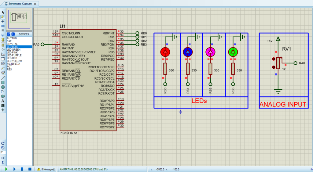
Proteus Configuration :

  • Open Proteus & Create New Project and click next

  • Click on Pick Device
  • Search for PIC16F877A & POT & LED-RED & LED- GREEN & LED-PINK &  LED-BLUE
  • Click on Terminal Mode then choose (DEFAULT & POWER &GROUND)
  • finally make the circuit below and start the simulation
Circuit diagram of PIC16F877 ADC in Proteus simulation.

That’s all!

If you have any questions or suggestions don’t hesitate to leave a comment below

You Might Also Like

Leave a Comment


Are you sure want to unlock this post?
Unlock left : 0
Are you sure want to cancel subscription?
-
00:00
00:00
Update Required Flash plugin
-
00:00
00:00