PIC16F877 16×2 LCD Interfacing: Step-by-Step Guide

by Marwen Maghrebi

In this article, we’ll show how to interface a PIC16F877 16×2 LCD with a microcontroller for easy data display

Key features of the project interfacing PIC16F877A with a 16×2 LCD.

Things used in this project

Software apps and online services:

1- MPLAB

2- Proteus 8

Enhancing Embedded Systems with a 16×2 Alphanumeric LCD and the PIC16F877 Microcontroller

Incorporating a PIC16F877 16×2 LCD into small embedded systems significantly improves user experience by offering a simple yet effective user interface. These LCDs are ideal for displaying text, numbers, and other essential information. Various LCD types feature different configurations, such as columns and rows, colored displays, and interfaces like parallel, SPI, and I2C. This article focuses on interfacing a PIC16F877 16×2 LCD with a 16-pin header, using the standard Hitachi HD44780 controller.

LCD Module Overview :

A typical 16×2
LCD module features 16 characters per line and two lines, each character being a 5×8 dot matrix. The module is controlled by the HD44780 controller, which handles the display operations and communicates with the master microcontroller unit (MCU).

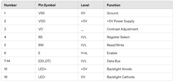
LCD Pinout and Functions:

A typical 16×2 LCD module includes a 16-pin header, with each pin serving a specific function.

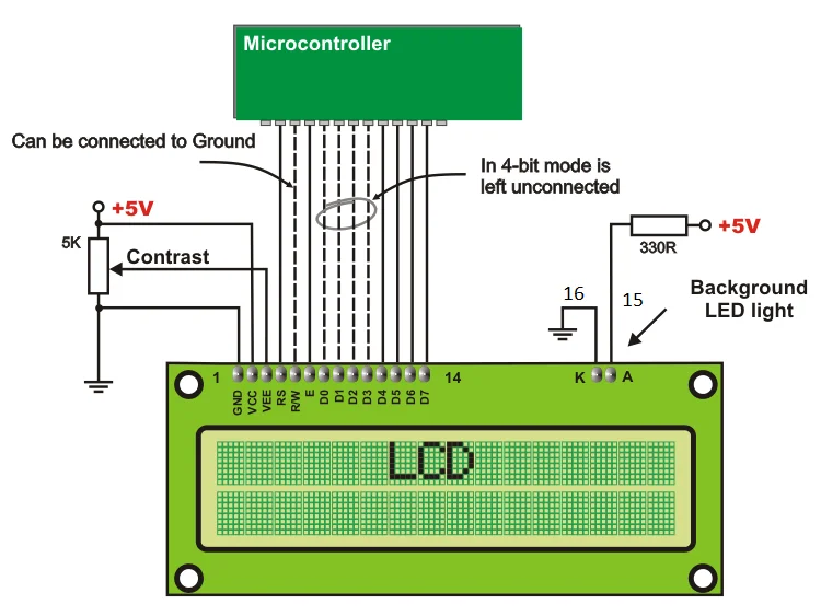
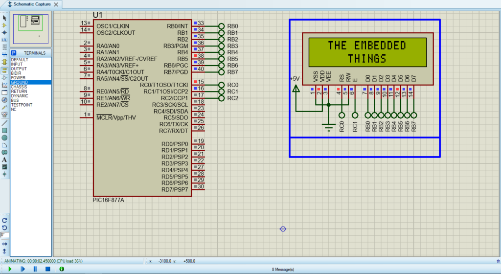
LCD Connection Diagram with Microcontroller :

The connection between the LCD and the PIC16F877A microcontroller is straightforward. A wiring diagram will be provided to illustrate the connections.

LCD Controller IC: Hitachi HD44780:

The Hitachi HD44780 controller manages the display operations, reducing the workload for the main MCU. It uses internal registers to store instructions and data, ensuring efficient display management.


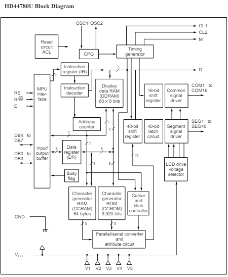
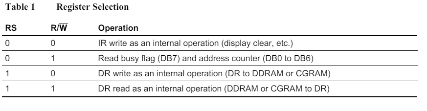
Internal Registers: IR and DR:

The HD44780 features two key registers:

  • Instruction Register (IR): Stores command codes and address info for Display Data RAM (DDRAM) and Character Generator RAM (CGRAM).
  • Data Register (DR): Temporarily holds data for DDRAM or CGRAM operations.

Display Data RAM (DDRAM):

DDRAM stores 8-bit character codes, with an 80×8-bit capacity (80 characters). Only 32 characters are visible at a time on the 16×2 LCD; the rest remain in DDRAM off-screen.

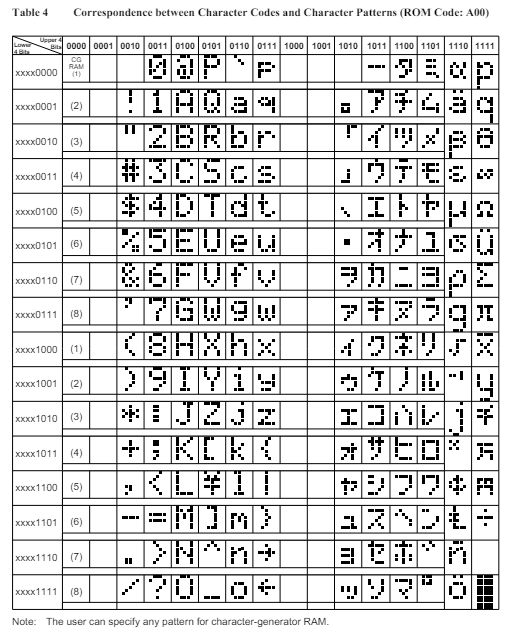
Character Generator ROM (CGROM):

CGROM contains predefined 5×8 or 5×10 dot character patterns, generating 208 5×8 dot and 32 5×10 dot characters. Users can also create custom characters, which will be covered in a later tutorial.

Character patterns from CGROM showing predefined 5×8 and 5×10 dot characters.

Character Generator RAM (CGRAM):

CGRAM allows users to define custom character patterns. For 5×8 dots, up to eight patterns can be stored, and for 5×10 dots, up to four patterns can be stored.

Busy Flag (BF):

The busy flag indicates if the HD44780 is performing an internal operation. When the busy flag is set (BF = 1), no new instructions are accepted. The flag is output to DB7 when RS = 0 and R/W = 1, and the next instruction should only be issued when BF = 0.

Address Counter (AC):

The address counter assigns addresses to DDRAM and CGRAM. It is automatically incremented or decremented after data operations, with the current address output to DB0-DB6 when RS = 0 and R/W = 1.
The LCD uses register selection to distinguish between command and data operations. The RS pin determines whether the data sent is an instruction (RS = 0) or data (RS = 1).
Address counter operation in LCD distinguishing command and data using RS pin.

Project name : Enhanced 8-bit LCD Interface for PIC16f877

This code demonstrates how to interface an LCD (Liquid Crystal Display) with a PIC microcontroller. It initializes the LCD, clears the screen, and prints messages on it. Additionally, it provides functions to control the cursor position and send commands or data to the LCD.

Code (in C using XC8 Compiler):

Configuration and LCD Interface Definitions

his part of the code includes configuration settings for the PIC microcontroller, such as oscillator settings and protection bits. It also defines constants for the LCD interface, including pin configurations for the data bus, enable pin, and RS pin. This section sets the groundwork for interacting with the LCD.

#include <xc.h>

#define _XTAL_FREQ  10000000UL      // 10MHz

// Configuration bits
#pragma config FOSC = HS            // Oscillator Selection bits (HS oscillator)
#pragma config WDTE = OFF           // Watchdog Timer Enable bit (WDT Disabled)
#pragma config PWRTE = OFF          // Power-up Timer Enable bit (PWRT disabled)
#pragma config CP = OFF             // FLASH Program Memory Code Protection bits (Code protection off)
#pragma config BOREN = ON           // Brown-out Reset Enable bit (BOR enabled)
#pragma config LVP = OFF            // Low Voltage In-Circuit Serial Programming Disable bit (RB3/PGM pin has PGM function; low-voltage programming enabled)
#pragma config CPD = OFF            // Data EE Memory Code Protection (Code Protection off)
#pragma config WRT = OFF            // FLASH Program Memory Write Disable (Unprotected program memory may be written to by EECON control)

// LCD pin definitions
#define LCD_BUS             PORTB   // Data bus for LCD (8 bits)
#define ENABLE_LCD          PORTCbits.RC1 // Enable pin of LCD
#define RS_LCD              PORTCbits.RC0 // RS pin of LCD

// Direction configuration for pins
#define LCD_BUS_DIRECTION   TRISB   // Data bus tristate register
#define ENABLE_DIRECTION    TRISCbits.TRISC1    // Enable pin tristate register
#define RS_DIRECTION        TRISCbits.TRISC0    // RS pin tristate register

// LCD line addresses
#define Line0               0x80
#define Line1               0xC0

LCD Function Implementations

Explanation: This section contains the function implementations for initializing the LCD, clearing the display, sending commands and data to the LCD, and printing strings to the LCD. These functions encapsulate the operations needed to control the LCD effectively.

// Function prototypes
void initializeLCD(void);
void clearLCD(void);
void sendCommandToLCD(unsigned char command);
void sendDataToLCD(unsigned char data);
void printToLCD(const char *string);
unsigned char moveCursorToPosition(unsigned char address);

void initializeLCD(void) {
    // Set pins as output
    ENABLE_DIRECTION    = 0;
    RS_DIRECTION        = 0;
    LCD_BUS_DIRECTION   = 0;

    // Write zero to pins and port
    ENABLE_LCD  = 0;
    RS_LCD      = 0;
    LCD_BUS     = 0;

    __delay_ms(10);          // 10 milliseconds delay

    // Initialization commands for LCD
    sendCommandToLCD(0x38); // Function set as given in datasheet
    sendCommandToLCD(0x0F); // Display ON; Cursor ON; Blink ON
    sendCommandToLCD(0x06); // Display shifting OFF
    clearLCD();             // Clear screen command
}

void clearLCD(void) {
    sendCommandToLCD(0x01); // Clear screen command
    __delay_ms(3);          // Delay for cursor to return home (minimum 3ms)
}

void sendCommandToLCD(unsigned char command) {
    RS_LCD = 0;             // Command RS must be low (0)
    LCD_BUS = command;      // Write command to data bus of LCD
    ENABLE_LCD = 1;         // Toggle Enable PIN to display data
    __delay_us(200);
    ENABLE_LCD = 0;
    __delay_us(200);
}

void sendDataToLCD(unsigned char data) {
    RS_LCD = 1;             // Data RS must be high (1)
    LCD_BUS = data;         // Write data to data bus of LCD
    ENABLE_LCD = 1;         // Toggle Enable PIN to display data
    __delay_us(200);
    ENABLE_LCD = 0;
    __delay_us(200);
}

void printToLCD(const char *string) {
    while(*string) {
        sendDataToLCD(*string++);   // Display data until string ends
    }
}

unsigned char moveCursorToPosition(unsigned char address) {
    // Valid addresses: 0x80 to 0xA8 for line one, 0xC0 to 0xE8 for line two
    if ((address >= 0x80 && address <= 0xA8) || (address >= 0xC0 && address <= 0xE8)) {
        sendCommandToLCD(address);
        return 1;
    } else {
        return 0;
    }
}

Main Function Execution Loop

Explanation: In this section, the main function initializes the LCD and enters an infinite loop that clears the LCD and displays a message on two lines. This loop demonstrates the usage of the defined functions to control the LCD and show dynamic conten

int main() {
    // Set pins as output
    ENABLE_DIRECTION    = 0;
    RS_DIRECTION        = 0;
    LCD_BUS_DIRECTION   = 0;

    // Write zero to pins and port
    ENABLE_LCD  = 0;
    RS_LCD      = 0;
    LCD_BUS     = 0;

    __delay_ms(10);          // 10 milliseconds delay

    // Initialization commands for LCD
    sendCommandToLCD(0x38); // Function set as given in datasheet
    sendCommandToLCD(0x0F); // Display ON; Cursor ON; Blink ON
    sendCommandToLCD(0x06); // Display shifting OFF
    sendCommandToLCD(0x01); // Clear screen command

    while(1) {
        clearLCD();
        __delay_ms(100);

        moveCursorToPosition(Line0);
        printToLCD("  THE EMBEDDED  ");

        moveCursorToPosition(Line1);
        printToLCD("     THINGS     ");
        __delay_ms(2000);           // 2 Second Delay.
    }
    return 0;           
}

Proteus Configuration :

  • Open Proteus & Create New Project and click next

  • Click on Pick Device
  • Search for PIC16F877A & LCD 16 * 2
  • Click on Terminal Mode then choose (DEFAULT & POWER &GROUND)
  • finally make the circuit below and start the simulation
Circuit diagram for interfacing PIC16F877A with a 16×2 LCD in Proteus simulation.

That’s all!

If you have any questions or suggestions don’t hesitate to leave a comment below

You Might Also Like

Leave a Comment


Are you sure want to unlock this post?
Unlock left : 0
Are you sure want to cancel subscription?
-
00:00
00:00
Update Required Flash plugin
-
00:00
00:00